Congratulations! I have an interesting problem. I have two variants of Chinese power supplies (photo below) for lighting. The interesting thing is that I don't have any of them in my hands to measure the actual voltage readings at the output of these units. As you can see, their output voltages range from a minimum of 36VDC to 95VDC. I need to control the brightness of the LEDs at the output.
I want to control it with the help of PWM, from the microcontroller ESP32. To do this, I plan to take the IRFB9N60APBF MOSFET.
ESP32 will protect the optocoupler from the voltage, for example 95V. And then I will control the high voltage by applying to the GATE of the transistor 95V. I read the datasheet on the MOSFETs, it seemed to me that it is possible. so that Vds = Vgs.
Is it possible to control the GATE of the transistor with such voltages?
I have attached the file and the diagram from falstad FalstadMOSFET_.circuitjs.txt (712 Байти)
. I apologize for my English right away. Thank you very much for your time!
Things tend to get iffy above 48V. In principle, yes, but component selection is going to be quite crucial.
Why are you using an optocoupler? Does the ESP32 supply need to be decoupled from the LED power supply? If not, just use a logic level MOSFET with a sufficiently high Vds rating.
Your circuit as drawn has several problems. You're exceeding the Vgs max rating of the MOSFET you selected. Your 10k gate pulldown resistor dissipates an unnecessarily high amount of power - and there's no need to switch the gate with 95V to begin with.
The 1k series resistor for your LED is puzzling; you show photos of LED drivers and the whole point of those is that they regulate the LED current without the need for additional components. The second photo shows an 850mA driver that will try to keep the LED power at exactly 850mA. The first photo doesn't show the LED current, but it should be part of it specs.
1)I understand, but I have no choice. So you should be prepared for the fact that the output of one of these LED drivers will have a maximum voltage of 95V.
2)I want to isolate the ESP32 from high voltages that can fall into the low voltage region due to a breakdown of the transistor's gate.
The ESP and the lighting will be powered from different sources. And with different voltage ratings.
After reading a little documentation, I saw that the Vgs parameter (in our case, Vgs = +/-30) can be exceeded, but this is not recommended (this is in the document below). In addition, since the difference between Vgs(th) = 3.3V and Vdc = 95V will be 95 - 3.3 = 91.7V, the case should heat up, this is because we do not fit into the range of Vgs = +/-30 at all. That is, there is a real risk of damage to the GATE due to such a large voltage difference. So, to reduce the difference in these voltages, I decided why not try to power the GATE directly from the LED driver, and for this I took another optocoupler?
I got this idea from this document, which I'll attach below. On page 10, in the Datasheet Extrapolation Example, there is an interesting calculation with a description.
3)When you say "You're exceeding the Vgs max rating of the MOSFET you selected", you mean that I'm exceeding the Vgs(th) rating, which is min 2V, max 4V. That is, in my case, Vgs(th) = 95V. That is, you do not see the point in controlling the GATE with 95V. Did I understand everything correctly? About the resistor a little later.
4)Regarding the 1k resistor. Don't mind me, I just needed to close the network in falstad, and in this program the LED will "burn out" without a resistor. In place of this LED and the 1k resistor, there will be an LED matrix.
That is the Threshold voltage, you need to exceed the MAX to get it to fully enhance. There is another aspect to Vgs, that is Gate-source voltage, which is the maximum voltage allowed on the gate in reference to the source. To turn it on you need to exceed Vgs max but stay below the Vgs (Gate-source voltage). There is a Vgs curve posted with most MOSFET data sheets, that will give you the parameters you need to meet.
I can't predict if PWM is going to work or not since you are "fighting" the constant-current supply which wants to put-out a constant 850mA DC. If it works "as expected", it will jump to its maximum voltage when the MOSFET is turned off, as it tries to push 850mA through an infinite resistance.
The "industrial standard" for dimming is 0-10VDC and most of them also work with 10V PWM. Some have the 10V built-in (so they can be dimmed manually by simply attaching a potentiometer). If the 10V is built-in you can use a simple transistor driver with the Arduino. A regular bipolar transistor is "easier" than a MOSFET in low-power applications because it can be fully turned-on (saturated) with less than 1V (Vbe).
I saw a "trick" once where the output of a constant-current supply was dimmed by "shorting it out" with PWM and a MOSFET. When the MOSFET is on it shorts the output, dropping the output to (nearly) zero volts, and the 850mA is "diverted" through the MOSFET. If the constant current supply is "well behaved" the voltage falls (theoretically-approximately) to zero volts and it happily continues to put-out 850mA.
Since there is (almost) no voltage, almost no power consumed (or wasted) except for any inefficiency in the constant current power supply. (You should NEVER short a normal constant-voltage power supply!)
But again, there is no guarantee that a constant-current power supply will survive being shorted with PWM...
That one has a dimming pot on the power supply. Dimming functionality is already provided out of the box. No need to add it; you're done.
If you want to have some kind of dimming through a microcontroller, I'm with @jim-p that it's a bad idea to try and do this with this driver. Buy a bare LED panel of your choice and get a driver with a PWM or 0-10V dimming input instead as @DVDdoug suggests.
A MOSFET generally fails with either DS short or with DS open. In the latter case, it will simply not work anymore. In the former case, the LED driver will dump 850mA through it, but probably it will go into a short-circuit protection. I don't see much of a risk of the 95V from the LED driver making its way into your microcontroller pin. If so, replace the $5 microcontroller.
Of course, design the circuit in such a way that the MOSFET doesn't fail in the first place.
No; you're confusing at least two sets of MOSFET parameters. Vgs(th) had nothing to do with this. Moreover, the voltage between gate and drain won't directly affect dissipation in the MOSFET. Vgs will influence Rds, and you make sure this is no problem by selecting a MOSFET that's fully on with a low Rds at the Vgs your application can provide.
It seems the attachment went missing, but see above; I suspect you're mixing a couple of things up. I agree with @gilshultz on this.
If you absolutely must use these existing LED drivers with a PWM control that is to be part of the current source of the LED driver, then you'd have to figure out first if the driver uses high or low side switching; the latter is far more likely, but no guarantees. You may get away with a PWM-ed MOSFET at the low side of the LED panel, but it's uncommon to do it this way and I really doubt it's a particularly good idea (see start of this post).
I am very grateful to you @gilshultz, @DVDdoug , @rsmls ! Unfortunately, I can't give you all a "Solution" tick, although each of you complemented each other.
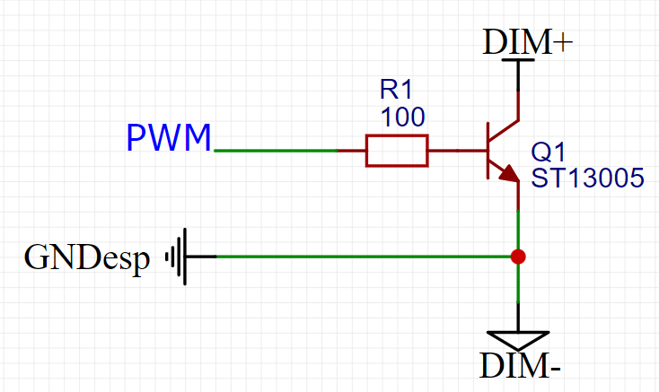
And finally. I chose the MeanWell driver for one of the LED matrices on the market. As your said, I will use this bipolar transistor. Please look at the diagram to see if I did everything right.
No worries, glad that you feel our comments were useful.
Please mark what @jim-p says above about the 10V PWM signal and note that the DIM+ pin does not appear to be internally pulled up to 10V inside the LED driver.
Since dimming with a resistor is possible, it's theoretically possible to use e.g. a MOSFET driven in its ohmic region to dim the driver, but I would emphatically not recommend this as it'll be wildly inaccurate/variable.
If you find that your dimming circuit doesn't work (which I expect), connect the collector of Q1 and DIM+ (this is the same node) to e.g. a 1k resistor and the other leg of the 1k resistor to a +10V power supply. You could make the 10V with a small DC-DC boost converter from the 3.3V or input voltage (5V likely) of your ESP board.
I had to work with these drivers. In the datasheet and in practice, they have the ability to be controlled with a 100kΩ potentiometer. I personally connected the potentiometer to DIM+/- and was able to adjust the brightness. But it didn't come to PWM, so I had doubts about choosing this particular model (also because I didn't find any videos or articles on the Internet where people control them with PWM). In addition, they are not cheap in my country, as for a university project, but thanks to you, I realized that there are no better/cheaper alternatives.
Thank you very much for your tips ! I hope to buy a driver and LED strip in the near future. I will experiment with a field-effect transistor, and if everything works out, I will post a post on the forum.