Hey fellas.
My goal is to create an array of infrared LED's to communicate the current time from my DS3231 RTC to another board. The goal is to reach a range of up to 30 meters.
My IR receiver will be the TSOP31236, which demodulates a 36kHz signal.
I plan to power the array with a separate battery pack, consisting of AA-batteries.
Furthermore I plan to use the MOSFET IPB123N10N3 G as my switch for the signal.
However at first I will try to send the signal with only one (1) LED, and scale it up from there.
You have to crawl before you can walk.
However I am unsure of how two modulate my signal at 36kHz.
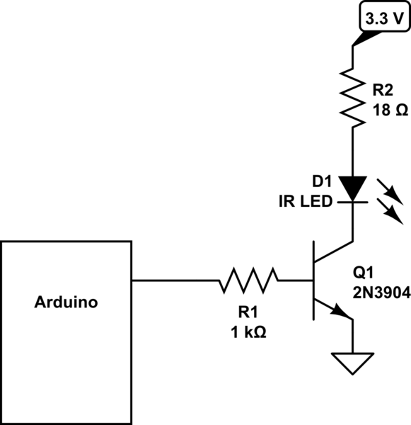
In this tutorial he uses tone() to generate the carrier signal, which is then used in conjunction with a BJT to encode the signal.

I recreated this circuit and I was able to send and receive my signal.
However as far as I can see, this system i harder to scale up, since the LED is powered directly by the Arduino, and if used in conjunction with batteries, it would drain them quickly, since current goes through the BJT when not used in the LED. (Might be wrong about this).
However inspired by this tutorial, I created the following circuit as a way to send my signal;

(I am sorry for my simple paint circuit, I hope you can make sense of it)
With the components:
Varta AA Battery
BC547A BJT
TSAL6200, 940nm, IR LED
IPB123N10N3 G, MOSFET
Arduino Uno
and with the following code;
#include <Time.h>
#include <DS3232RTC.h>
#include <SoftwareSerial.h>
#define cr_pin 9 //To use in the carrier signal

// Using pin10 and pin11 for serial, but inverted
SoftwareSerial mySerial (10, 11, true);

void setup() {
       //To ensure the MOSFET is in ON-stage
       pinMode(11, OUTPUT);

       // Start the serial port
       mySerial.begin(4800);

       //Start the carrier signal at 36kHz
       tone(cr_pin, 36000);

       // RTC stuff
       setSyncProvider(RTC.get);
}
void loop() {


      if (hour() < 10)//added code to give leading zeros
        mySerial.print("0");
      mySerial.print(hour());


      if (minute() < 10)//added code to give leading zeros
        mySerial.print("0");
      mySerial.print(minute());


      if (second() < 10)//added code to give leading zeros
        mySerial.print("0");
      mySerial.println(second());

      //One second delay
      delay (1000);
  }
The idea with this is using tone() on pin9 in conjunction with the BJT to create the carrier signal at 36kHz.
Then I use pin11 in conjunction with my MOSFET to encode my signal on the carrier.
The reason for the inverted logic was to keep the MOSFET off when not sending a signal, to save battery power.
However as I tried to power this circuit, things started to smell funky, and I quickly turned it off again. At this point I am unsure of what component(s) I fried, if any. Probably the BJT if I should guess.
I must have made wrong calculations and/or decisions along the way.
So can the circuit be tweaked, or is this solution completely idiotic?
If this circuit is unusable, how could I instead modulate and send my signal, so it can be received by the TSOP31236, and with the circuit being 'upscale-able' by adding more LED's and batteries as necessary?
Sorry for the long post and questions, and thank you, if you took the time to read it all. : )