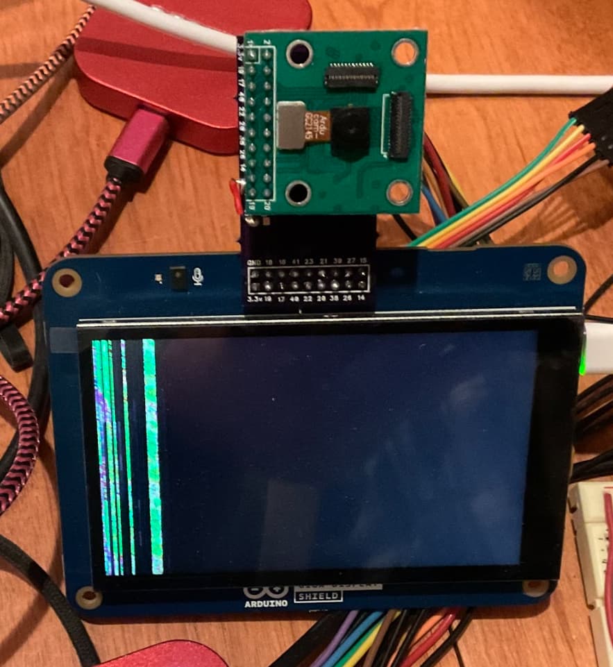
GigaR1 and gc2145 Arducam changes ?

Looks like there may be some recent incompatibility with the GigaR1 and gc2145 ?

used the tutorial from here:

https://docs.arduino.cc/tutorials/giga-r1-wifi/giga-camera/

I think I've modified what needs to be matched to the Processing code, but I'm still getting no image. I've not used Processing before, so it very well may be user error, but the tutorial is pretty sparse, and could perhaps use some fleshing out. The current code in the tutorial, is also not the same as what is in the current CameraCaptureRawBytes example, and does not work, returning an error related to one of the ov767x camera's which I think can be fixed by commenting them out if you aren't using that camera. I changed the baudrate in Processing to match the Arduino example at 115200

I tried the sketch with camera set to RGB565 and made what looked like the appropriate changes to the Processing sketch, but that errored out, so I changed it to useGrayscale, which does not error, but also does not produce an image.

Processing debug sticks here with debugger busy on:

myPort = new Serial(this, "/dev/cu.usbmodem144201", baudRate); // Mac

*** update ***

In Processing debug, I am now getting a Connection timed out.

I've read a few possible solutions, such as adding a 50ms delay, so far that has not worked.

Arduino code:

#include "camera.h"

#ifdef ARDUINO_NICLA_VISION
  #include "gc2145.h"
  GC2145 galaxyCore;
  Camera cam(galaxyCore);
  #define IMAGE_MODE CAMERA_GRAYSCALE
#elif defined(ARDUINO_PORTENTA_H7_M7)
  // uncomment the correct camera in use
  #include "hm0360.h"
  HM0360 himax;
  
  // #include "himax.h"
  // HM01B0 himax;
  // Camera cam(himax);

  Camera cam(himax);
  #define IMAGE_MODE CAMERA_GRAYSCALE
#elif defined(ARDUINO_GIGA)
  #include "ov767x.h"
  // uncomment the correct camera in use
  OV7670 ov767x;
  // OV7675 ov767x;
  Camera cam(ov767x);
  #define IMAGE_MODE CAMERA_RGB565
#else
#error "This board is unsupported."
#endif

/*
Other buffer instantiation options:
  FrameBuffer fb(0x30000000);
  FrameBuffer fb(320,240,2);

If resolution higher than 320x240 is required, please use external RAM via
  #include "SDRAM.h"
  FrameBuffer fb(SDRAM_START_ADDRESS);
  ...
  // and adding in setup()
  SDRAM.begin();
*/
FrameBuffer fb;

unsigned long lastUpdate = 0;


void blinkLED(uint32_t count = 0xFFFFFFFF)
{
  pinMode(LED_BUILTIN, OUTPUT);
  while (count--) {
    digitalWrite(LED_BUILTIN, LOW);  // turn the LED on (HIGH is the voltage level)
    delay(50);                       // wait for a second
    digitalWrite(LED_BUILTIN, HIGH); // turn the LED off by making the voltage LOW
    delay(50);                       // wait for a second
  }
}

void setup() {
  // Init the cam QVGA, 30FPS
  if (!cam.begin(CAMERA_R320x240, IMAGE_MODE, 30)) {
    blinkLED();
  }

  blinkLED(5);
}

void loop() {
  if(!Serial) {    
    Serial.begin(115200);
    while(!Serial);
  }

  // Time out after 2 seconds, which sets the (constant) frame rate
  bool timeoutDetected = millis() - lastUpdate > 2000;
  
  // Wait for sync byte and timeout
  // Notice that this order must be kept, or the sync bytes will be
  // consumed prematurely
  if ((!timeoutDetected) || (Serial.read() != 1))
  {
    return;
  }

  lastUpdate = millis();
  
  // Grab frame and write to serial
  if (cam.grabFrame(fb, 3000) == 0) {
    Serial.write(fb.getBuffer(), cam.frameSize());
  } else {
    blinkLED(20);
  }
}

Processing sketch:

/*
  Use with the Examples -> CameraCaptureRawBytes Arduino sketch.
  This example code is in the public domain.
*/

import processing.serial.*;
import java.nio.ByteBuffer;
import java.nio.ByteOrder;

Serial myPort;

// must match resolution used in the Arduino sketch
final int cameraWidth = 320;
final int cameraHeight = 240;

// Must match the image mode in the Arduino sketch
final boolean useGrayScale = true;

// Must match the baud rate in the Arduino sketch
final int baudRate = 115200;

final int cameraBytesPerPixel = useGrayScale ? 1 : 2;
final int cameraPixelCount = cameraWidth * cameraHeight;
final int bytesPerFrame = cameraPixelCount * cameraBytesPerPixel;
final int timeout =  int((bytesPerFrame / float(baudRate / 10)) * 1000 * 2); // Twice the transfer rate

PImage myImage;
byte[] frameBuffer = new byte[bytesPerFrame];
int lastUpdate = 0;
boolean shouldRedraw = false;

void setup() {
  size(320, 240);  

  // If you have only ONE serial port active you may use this:
  //myPort = new Serial(this, Serial.list()[0], baudRate);          // if you have only ONE serial port active

  // If you know the serial port name
  //myPort = new Serial(this, "COM5", baudRate);                    // Windows
  //myPort = new Serial(this, "/dev/ttyACM0", baudRate);            // Linux
  myPort = new Serial(this, "/dev/cu.usbmodem144201", baudRate);     // Mac

  // wait for a full frame of bytes
  myPort.buffer(bytesPerFrame);  

  myImage = createImage(cameraWidth, cameraHeight, ALPHA);
  
  // Let the Arduino sketch know we're ready to receive data
  myPort.write(1);
}

void draw() {
  // Time out after a few seconds and ask for new data
  if(millis() - lastUpdate > timeout) {
    println("Connection timed out.");    
    myPort.clear();
    myPort.write(1);
  }
  
  if(shouldRedraw){    
    PImage img = myImage.copy();
    img.resize(320, 240);
    image(img, 0, 0);
    shouldRedraw = false;
  }
}

int[] convertRGB565ToRGB888(short pixelValue){  
  //RGB565
  int r = (pixelValue >> (6+5)) & 0x01F;
  int g = (pixelValue >> 5) & 0x03F;
  int b = (pixelValue) & 0x01F;
  //RGB888 - amplify
  r <<= 3;
  g <<= 2;
  b <<= 3; 
  return new int[]{r,g,b};
}

void serialEvent(Serial myPort) {  
  lastUpdate = millis();
  
  // read the received bytes
  myPort.readBytes(frameBuffer);

  // Access raw bytes via byte buffer  
  ByteBuffer bb = ByteBuffer.wrap(frameBuffer);
  
  // Ensure proper endianness of the data for > 8 bit values.
  // The 1 byte bb.get() function will always return the bytes in the correct order.
  bb.order(ByteOrder.BIG_ENDIAN);

  int i = 0;

  while (bb.hasRemaining()) {
    if(useGrayScale){
      // read 8-bit pixel data
      byte pixelValue = bb.get();

      // set pixel color
      myImage.pixels[i++] = color(Byte.toUnsignedInt(pixelValue));
    } else {
      // read 16-bit pixel data
      int[] rgbValues = convertRGB565ToRGB888(bb.getShort());

      // set pixel RGB color
      myImage.pixels[i++] = color(rgbValues[0], rgbValues[1], rgbValues[2]);
    }       
  }
  
  myImage.updatePixels();
  
  // Ensures that the new image data is drawn in the next draw loop
  shouldRedraw = true;
  
  // Let the Arduino sketch know we received all pixels
  // and are ready for the next frame
  myPort.write(1);
}

In the Processing Sketch it has this line of code, which needs to change - as in, set to false as you are wanting to use RGB565:

// Must match the image mode in the Arduino sketch
final boolean useGrayScale = true;

If I am reading your sketch properly, on Giga it will try to load code for OV7670, not gc2145.

Well, I have it set to use GrayScale, as the alternative did not work either.

All the camera types are uncommented, so I'm assuming it will just use the correct camera, like any other sketch that has code for multiple devices like multiple blinks for nano 33 ble and rp2040. The sketch should use the correct code for the present device ?

I think I did try to comment out the others and that resulted in a "This board is unsupported"

not sure this is a solution but for the GigaCameraDisplay example I have the camera working with this:

#include "arducam_dvp.h"
#include "Arduino_H7_Video.h"
#include "dsi.h"
#include "SDRAM.h"

// This example only works with Greyscale cameras (due to the palette + resize&rotate algo)


#define ARDUCAM_CAMERA_GC2145

//#ifdef ARDUCAM_CAMERA_HM01B0
//#include "Himax_HM01B0/himax.h"
//HM01B0 himax;
//Camera cam(himax);
//#define IMAGE_MODE CAMERA_GRAYSCALE
//#elif defined(ARDUCAM_CAMERA_HM0360)
//#include "Himax_HM0360/hm0360.h"
//HM0360 himax;
//Camera cam(himax);
//#define IMAGE_MODE CAMERA_RGB565
//#include "OV7670/ov767x.h"
//OV7675 ov767x;
//Camera cam(ov767x);
#define IMAGE_MODE CAMERA_RGB565
//#elif defined(ARDUCAM_CAMERA_GC2145)
#include "GC2145/gc2145.h"
GC2145 galaxyCore;
Camera cam(galaxyCore);
#define IMAGE_MODE CAMERA_RGB565


// The buffer used to capture the frame
FrameBuffer fb;
// The buffer used to rotate and resize the frame
FrameBuffer outfb;
// The buffer used to rotate and resize the frame
Arduino_H7_Video Display(800, 480, GigaDisplayShield);

void blinkLED(uint32_t count = 0xFFFFFFFF)
{
  pinMode(LED_BUILTIN, OUTPUT);
  while (count--) {
    digitalWrite(LED_BUILTIN, LOW);  // turn the LED on (HIGH is the voltage level)
    delay(50);                       // wait for a second
    digitalWrite(LED_BUILTIN, HIGH); // turn the LED off by making the voltage LOW
    delay(50);                       // wait for a second
  }
}

uint32_t palette[256];

void setup() {
  // Init the cam QVGA, 30FPS
  if (!cam.begin(CAMERA_R320x240, IMAGE_MODE, 30)) {
    blinkLED();
  }

  // Setup the palette to convert 8 bit greyscale to 32bit greyscale
  for (int i = 0; i < 256; i++) {
    palette[i] = 0xFF000000 | (i << 16) | (i << 8) | i;
  }

  Display.begin();

  if (IMAGE_MODE == CAMERA_GRAYSCALE) {
    dsi_configueCLUT((uint32_t*)palette);
  }
  outfb.setBuffer((uint8_t*)SDRAM.malloc(1024 * 1024));

  // clear the display (gives a nice black background)
  dsi_lcdClear(0);
  dsi_drawCurrentFrameBuffer();
  dsi_lcdClear(0);
  dsi_drawCurrentFrameBuffer();
}

#define HTONS(x)    (((x >> 8) & 0x00FF) | ((x << 8) & 0xFF00))

void loop() {

  // Grab frame and write to another framebuffer
  if (cam.grabFrame(fb, 3000) == 0) {

    // double the resolution and transpose (rotate by 90 degrees) in the same step
    // this only works if the camera feed is 320x240 and the area where we want to display is 640x480
    for (int i = 0; i < 320; i++) {
      for (int j = 0; j < 240; j++) {
        if (IMAGE_MODE == CAMERA_GRAYSCALE) {
          ((uint8_t*)outfb.getBuffer())[j * 2 + (i * 2) * 480] = ((uint8_t*)fb.getBuffer())[i + j * 320];
          ((uint8_t*)outfb.getBuffer())[j * 2 + (i * 2) * 480 + 1] = ((uint8_t*)fb.getBuffer())[i + j * 320];
          ((uint8_t*)outfb.getBuffer())[j * 2 + (i * 2 + 1) * 480] = ((uint8_t*)fb.getBuffer())[i + j * 320];
          ((uint8_t*)outfb.getBuffer())[j * 2 + (i * 2 + 1) * 480 + 1] = ((uint8_t*)fb.getBuffer())[i + j * 320];
        } else {
          ((uint16_t*)outfb.getBuffer())[j * 2 + (i * 2) * 480] = HTONS(((uint16_t*)fb.getBuffer())[i + j * 320]);
          ((uint16_t*)outfb.getBuffer())[j * 2 + (i * 2) * 480 + 1] = HTONS(((uint16_t*)fb.getBuffer())[i + j * 320]);
          ((uint16_t*)outfb.getBuffer())[j * 2 + (i * 2 + 1) * 480] = HTONS(((uint16_t*)fb.getBuffer())[i + j * 320]);
          ((uint16_t*)outfb.getBuffer())[j * 2 + (i * 2 + 1) * 480 + 1] = HTONS(((uint16_t*)fb.getBuffer())[i + j * 320]);
        }
      }
    }
    dsi_lcdDrawImage((void*)outfb.getBuffer(), (void*)dsi_getCurrentFrameBuffer(), 480, 640, IMAGE_MODE == CAMERA_GRAYSCALE ? DMA2D_INPUT_L8 : DMA2D_INPUT_RGB565);
    dsi_drawCurrentFrameBuffer();
  } else {
    blinkLED(20);
  }
}

With the current release, the:

Camera example: GigaCameraDisplay, does work now by editing
and change:
#define ARDUCAM_CAMERA_GC2145

Which does grab a frame, rotate it and display it on the screen :smiley:
The image should probably be rotated 180 degrees, but...

However it is only reading in a 320x240 pixel image or 76.8K pixels.
The camera is capable of 1600x1200 pixels or about 19.2M pixels

I am curious how doable is it to at least read in 640x480 pixels (VGA) and not have to sample up during the rotation:

The system has defines for this:

enum {
    CAMERA_R160x120     = 0,   /* QQVGA Resolution   */
    CAMERA_R320x240     = 1,   /* QVGA Resolution    */
    CAMERA_R320x320     = 2,   /* 320x320 Resolution */
    CAMERA_R640x480     = 3,   /* VGA                */
    CAMERA_R800x600     = 5,   /* SVGA               */
    CAMERA_R1600x1200   = 6,   /* UXGA               */
    CAMERA_RMAX                /* Sentinel value */
};

So I tried CAMERA_R640x480

If you try it, you first run into a fault (blinking pattern).
Why, the system failed to allocate the fb object in memory.

I was able to get farther by allocating it also in SDRAM like:

  uint8_t *fb_buf = (uint8_t *)((((uint32_t)SDRAM.malloc(CAMERA_WIDTH * CAMERA_HEIGHT * 2 + 31)) + 31) & 0xfffffff0l);
  fb.setBuffer(fb_buf);
  Serial.print("FB Buffer: ");
  Serial.println((uint32_t)fb_buf, HEX);

  outfb.setBuffer((uint8_t *)SDRAM.malloc(OUTFB_WIDTH * OUTFB_HEIGHT * 2));
  Serial.print("OutFB Buffer: ");
  Serial.print((uint32_t)outfb.getBuffer(), HEX);

Which gets farther. Obviously you need to change the rotate code to not double up the pixels... But not working overly well. There is probably an issue where
reading into and using SDRAM is too slow.

In the case with these displays, would like, if you could actually have the camera read in 800 by 480 and maybe internally do the rotate for you... Still playing.

Note: I have my copy of the library hacked up some, to for example print out the camera registers after the camera has been started...

  galaxyCore.debug(Serial);
  galaxyCore.printRegs();

Note: the printRegs() is not in the library now. There are some for some of the cameras not this one. I also hacked it up to get register names:


*** Camera Registers ***
(0x3): (0x4 - 4)	: Exposure[12:8]
(0x4): (0x38 - 56)	: Exposure[7:0]
(0x5): (0x1 - 1)	: buf_CISCTL_capt_hb[11:8]
(0x6): (0x1C - 28)	: buf_CISCTL_capt_hb[7:0]
(0x7): (0x0 - 0)	: buf_CISCTL_capt_vb[12:8]
(0x8): (0x32 - 50)	: buf_CISCTL_capt_vb[7:0]
(0x9): (0x0 - 0)	: buf_CISCTL_capt_row_start[10:8]
(0xA): (0xF0 - 240)	: buf_CISCTL_capt_row_start[7:0]
(0xB): (0x1 - 1)	: buf_CISCTL_capt_col_start[10:8 ]
(0xC): (0x40 - 64)	: buf_CISCTL_capt_col_start[7:1]
(0xD): (0x2 - 2)	: buf_CISCTL_capt_win_height[10:8]
(0xE): (0xD8 - 216)	: buf_CISCTL_capt_win_height[7:0]
(0xF): (0x3 - 3)	: buf_CISCTL_capt_win_width[10:8]
(0x10): (0xD0 - 208)	: buf_CISCTL_capt_win_width[7:1]
(0x11): (0x0 - 0)
(0x12): (0x1D - 29)
(0x13): (0x0 - 0)
(0x14): (0x0 - 0)
(0x15): (0x0 - 0)
(0x16): (0xC1 - 193)
(0x17): (0x14 - 20)	: Analog mode1
(0x18): (0x22 - 34)	: Analog mode2
(0x19): (0xE - 14)
(0x1A): (0x1 - 1)
(0x1B): (0x4B - 75)
(0x1C): (0x7 - 7)
(0x1D): (0x10 - 16)
(0x1E): (0x88 - 136)
(0x1F): (0x78 - 120)
(0x20): (0x3 - 3)	: Analog mode3
(0x21): (0x40 - 64)
(0x22): (0xA0 - 160)
(0x23): (0x1 - 1)
(0x24): (0x16 - 22)	: Driver mode
(0x25): (0x1 - 1)
(0x26): (0x10 - 16)
(0x27): (0x32 - 50)
(0x28): (0xB7 - 183)
(0x29): (0xF - 15)
(0x2A): (0x0 - 0)
(0x2B): (0x0 - 0)
(0x2C): (0x0 - 0)
(0x2D): (0x60 - 96)
(0x2E): (0x4 - 4)
(0x2F): (0x0 - 0)
(0x30): (0x1 - 1)
(0x31): (0x90 - 144)
(0x32): (0x13 - 19)
(0x33): (0x6 - 6)
(0x34): (0x1 - 1)
(0x35): (0x0 - 0)
(0x36): (0x0 - 0)
(0x37): (0x0 - 0)
(0x38): (0x0 - 0)
(0x39): (0x0 - 0)
(0x3A): (0x0 - 0)
(0x3B): (0x0 - 0)
(0x3C): (0x0 - 0)
(0x3D): (0x0 - 0)
(0x3E): (0x0 - 0)
(0x3F): (0x0 - 0)	: dark_current_st able_th
(0x40): (0x42 - 66)	: Blk_mode1
(0x41): (0x0 - 0)
(0x42): (0xFF - 255)	: BLK_limit_value
(0x43): (0x5B - 91)	: BLK_fame_cnt_TH
(0x44): (0x9B - 155)
(0x45): (0x9C - 156)
(0x46): (0xAF - 175)
(0x47): (0xAF - 175)
(0x48): (0xAE - 174)
(0x49): (0xAE - 174)
(0x4A): (0x9A - 154)
(0x4B): (0x9B - 155)
(0x4C): (0x0 - 0)
(0x4D): (0x0 - 0)
(0x4E): (0x0 - 0)
(0x4F): (0x0 - 0)
(0x50): (0x0 - 0)
(0x51): (0x0 - 0)
(0x52): (0x0 - 0)
(0x53): (0x0 - 0)
(0x54): (0xF3 - 243)
(0x55): (0xC4 - 196)
(0x56): (0xEA - 234)
(0x57): (0xC5 - 197)
(0x58): (0x5 - 5)
(0x59): (0xE3 - 227)
(0x5A): (0xD - 13)
(0x5B): (0xDE - 222)
(0x5C): (0x0 - 0)	: Exp_rate_darkc
(0x5D): (0x28 - 40)
(0x5E): (0x0 - 0)	: current_G1_offset_odd_ratio
(0x5F): (0x0 - 0)	: current_G1_offset_even_ratio
(0x60): (0x0 - 0)	: current_R1_offset_odd_ratio
(0x61): (0x0 - 0)	: current_R1_offset_even_ratio
(0x62): (0x0 - 0)	: current_B1_offset_odd_ratio
(0x63): (0x0 - 0)	: current_B1_offset_even_ratio
(0x64): (0x0 - 0)	: current_G2_offset_odd_ratio
(0x65): (0x0 - 0)	: current_G2_offset_even_ratio
(0x66): (0x20 - 32)	: Dark_current_G1_ratio
(0x67): (0x20 - 32)	: Dark_current_R_ratio
(0x68): (0x20 - 32)	: Dark_current_B_ratio
(0x69): (0x20 - 32)	: Dark_current_G2_ratio
(0x6A): (0x8 - 8)	: manual_G1_odd_offset
(0x6B): (0x8 - 8)	: manual_G1_even_offset
(0x6C): (0x8 - 8)	: manual_R1_odd_offset
(0x6D): (0x8 - 8)	: manual_R1_even_offset
(0x6E): (0x8 - 8)	: manual_B2_odd_offset
(0x6F): (0x8 - 8)	: manual_B2_even_offset
(0x70): (0x8 - 8)	: manual_G2_odd_offset
(0x71): (0x8 - 8)	: manual_G2_even_offset
(0x72): (0xF0 - 240)	: BLK_DD_thBLK_various_th
(0x73): (0x10 - 16)
(0x74): (0x10 - 16)
(0x75): (0x0 - 0)
(0x76): (0x0 - 0)
(0x77): (0xFF - 255)
(0x78): (0x0 - 0)
(0x79): (0x0 - 0)
(0x7A): (0xA3 - 163)
(0x7B): (0x0 - 0)
(0x7C): (0x0 - 0)
(0x7D): (0x0 - 0)
(0x7E): (0x3C - 60)
(0x7F): (0x0 - 0)
(0x80): (0x7F - 127)	: Block_enable1
(0x81): (0x26 - 38)	: Block_enable2
(0x82): (0xFA - 250)	: Block enable
(0x83): (0x0 - 0)	: Special effect
(0x84): (0x6 - 6)	: Output format
(0x85): (0x8 - 8)	: Frame start
(0x86): (0x23 - 35)	: Sync mode
(0x87): (0x0 - 0)	: block_enable3_buf
(0x88): (0x3 - 3)	: module_gating
(0x89): (0x3 - 3)	: bypass_mode
(0x8A): (0x0 - 0)
(0x8B): (0x0 - 0)
(0x8C): (0x0 - 0)	: debug_mode2
(0x8D): (0x1 - 1)	: Debug_mode3
(0x8E): (0x6 - 6)
(0x8F): (0x50 - 80)
(0x90): (0x1 - 1)	: Crop enable
(0x91): (0x0 - 0)	: out_win_y1[10:8]
(0x92): (0x0 - 0)	: out_win_y1 [7:0]
(0x93): (0x0 - 0)	: out_win_x1[10:8]
(0x94): (0x0 - 0)	: out_win_x1[7:0]
(0x95): (0x0 - 0)	: out_win_height[10:8]
(0x96): (0xF0 - 240)	: out_win_height[7:0]
(0x97): (0x1 - 1)	: out_win_width[10:8]
(0x98): (0x40 - 64)	: out_win_width[7:0]
(0x99): (0x33 - 51)	: subsample
(0x9A): (0xE - 14)	: Subsample mode
(0x9B): (0x0 - 0)	: Sub_row_N1
(0x9C): (0x0 - 0)	: Sub_row_N2
(0x9D): (0x0 - 0)	: Sub_row_N3
(0x9E): (0x0 - 0)	: Sub_row_N4
(0x9F): (0x0 - 0)	: Sub_col_N1
(0xA0): (0x0 - 0)	: Sub_col_N2
(0xA1): (0x0 - 0)	: Sub_col_N3
(0xA2): (0x0 - 0)	: Sub_col_N4
(0xA3): (0x80 - 128)	: channel_gain_G1_odd
(0xA4): (0x80 - 128)	: channel_gain_G1_even
(0xA5): (0x80 - 128)	: channel_gain_R1_odd
(0xA6): (0x80 - 128)	: channel_gain_R1_even
(0xA7): (0x80 - 128)	: channel_gain_B2_odd
(0xA8): (0x80 - 128)	: channel_gain_
(0xA9): (0x80 - 128)	: channel_gain_G2_odd
(0xAA): (0x80 - 128)	: channel_gain_G2_even
(0xAB): (0x0 - 0)
(0xAC): (0x0 - 0)
(0xAD): (0x80 - 128)	: R_ratio
(0xAE): (0x80 - 128)	: G_ratio
(0xAF): (0x80 - 128)	: B_ratio
(0xB0): (0x55 - 85)	: Global_gain
(0xB1): (0x27 - 39)	: Auto_pregain
(0xB2): (0x40 - 64)	: Auto_postgain
(0xB3): (0x40 - 64)	: AWB_R_gain
(0xB4): (0x56 - 86)	: AWB_G_gain
(0xB5): (0x9E - 158)	: AWB_B_gain

Note: I am only printing out what might be in Page 0 of registers, there are 4 pages. The version I am trying on Teensy, I have debug output from writing to the registers that shows all of the writes>

The names of the registers I used excel to grab the tables out of the camera reference datasheet, which you can download from the Nicla Vision document page:

Nicla Vision | Arduino Documentation

Yeah, I tried the other example with the correct camera name, and got to the issues with the SDRAM, and I was pretty immediately out of my depth.

It's strange the emphasis the author put into rotating the image in the other sketch.

super educational to see how much you dug into it.

I'm a good ways away from the ML part of the project assuming I actually get there, so I'm putting this on the back burner for now, as creating a UI is the next step for me. When I do get there, I'll be remoting the camera, so I'll probably just rotate the camera physically if that doesn't cause an issue.

Quick update, I am wondering if anything > 320x240 works at all on the GIGA?
And also even if 320x240 works if the camera buffer is in SDRAM?

Here is a reasonably simple sketch:

#include "arducam_dvp.h"
#include "Arduino_H7_Video.h"
#include "dsi.h"
#include "SDRAM.h"

// This example only works with Greyscale cameras (due to the palette + resize&rotate algo)
#define ARDUCAM_CAMERA_GC2145

#ifdef ARDUCAM_CAMERA_HM01B0
#include "Himax_HM01B0/himax.h"
HM01B0 himax;
Camera cam(himax);
#define IMAGE_MODE CAMERA_GRAYSCALE
#elif defined(ARDUCAM_CAMERA_HM0360)
#include "Himax_HM0360/hm0360.h"
HM0360 himax;
Camera cam(himax);
#define IMAGE_MODE CAMERA_GRAYSCALE
#elif defined(ARDUCAM_CAMERA_OV767X)
#include "OV7670/ov767x.h"
// OV7670 ov767x;
OV7675 ov767x;
Camera cam(ov767x);
#define IMAGE_MODE CAMERA_RGB565
#elif defined(ARDUCAM_CAMERA_GC2145)
#include "GC2145/gc2145.h"
GC2145 galaxyCore;
Camera cam(galaxyCore);
#define IMAGE_MODE CAMERA_RGB565
#endif

// The buffer used to capture the frame
FrameBuffer fb;

// The buffer used to rotate and resize the frame
Arduino_H7_Video Display(800, 480, GigaDisplayShield);

void blinkLED(uint32_t count = 0xFFFFFFFF) {
  pinMode(LED_BUILTIN, OUTPUT);
  while (count--) {
    digitalWrite(LED_BUILTIN, LOW);   // turn the LED on (HIGH is the voltage level)
    delay(50);                        // wait for a second
    digitalWrite(LED_BUILTIN, HIGH);  // turn the LED off by making the voltage LOW
    delay(50);                        // wait for a second
  }
}

uint32_t palette[256];

void setup() {
  // Init the cam QVGA, 30FPS
  while (!Serial && millis() < 4000) {}
  Serial.begin(115200);
  galaxyCore.debug(Serial);
  // CAMERA_R160x120     = 0,   /* QQVGA Resolution   */
  // CAMERA_R320x240     = 1,   /* QVGA Resolution    */
  // CAMERA_R320x320     = 2,   /* 320x320 Resolution */
  // CAMERA_R640x480     = 3,   /* VGA                */
  // CAMERA_R800x600     = 5,   /* SVGA               */
  // CAMERA_R1600x1200   = 6,   /* UXGA               */
  // CAMERA_RMAX                /* Sentinel value */
  #define CAMERA_WIDTH 640
  #define CAMERA_HEIGHT 480
  if (!cam.begin(CAMERA_R640x480, IMAGE_MODE, 30)) {
    blinkLED();
  }
  galaxyCore.printRegs();

  // Setup the palette to convert 8 bit greyscale to 32bit greyscale
  for (int i = 0; i < 256; i++) {
    palette[i] = 0xFF000000 | (i << 16) | (i << 8) | i;
  }


  Display.begin();

  if (IMAGE_MODE == CAMERA_GRAYSCALE) {
    dsi_configueCLUT((uint32_t *)palette);
  }
  // big enough for full screen.
  #if CAMERA_WIDTH > 320
  uint8_t *fb_buf = (uint8_t *)((((uint32_t)SDRAM.malloc(CAMERA_WIDTH * CAMERA_HEIGHT * 2 + 31)) + 31) & 0xfffffff0l);
  memset(fb_buf, 0, CAMERA_WIDTH * CAMERA_HEIGHT * 2);
  fb.setBuffer(fb_buf);
  #endif
  Serial.print("FB Buffer: ");

  // clear the display (gives a nice black background)
  dsi_lcdClear(0);
  dsi_drawCurrentFrameBuffer();
  dsi_lcdClear(0);
  dsi_drawCurrentFrameBuffer();
}

inline uint16_t HTONS(uint16_t x) {
  return (((x >> 8) & 0x00FF) | ((x << 8) & 0xFF00));
}

void loop() {

  // Grab frame and write to another framebuffer
    SCB_CleanInvalidateDCache();
  if (cam.grabFrame(fb, 3000) == 0) {

    // double the resolution and transpose (rotate by 90 degrees) in the same step
    // this only works if the camera feed is 320x240 and the area where we want to display is 640x480
    uint16_t *frame_in = (uint16_t *)fb.getBuffer();
    SCB_CleanInvalidateDCache();
    //for (int ii = 0; ii < (1600 * 1200); ii++) frame_in[ii] = HTONS(frame_in[ii]);
    // lets clip the image to 480x480
    #if CAMERA_WIDTH < 480
    for (int ii = 0; ii < (CAMERA_WIDTH * CAMERA_HEIGHT); ii++) frame_in[ii] = HTONS(frame_in[ii]);
    SCB_CleanInvalidateDCache();
    dsi_lcdDrawImage((void *)fb.getBuffer(), (void *)dsi_getCurrentFrameBuffer(), CAMERA_WIDTH, CAMERA_HEIGHT, IMAGE_MODE == CAMERA_GRAYSCALE ? DMA2D_INPUT_L8 : DMA2D_INPUT_RGB565);
    #else
    for (int y = 0; y < 480; y++) {
      for (int x = 0; x < 480; x++) {
        frame_in[y * 480 + x] = HTONS(frame_in[y * CAMERA_WIDTH + x]);
      }
    }
    dsi_lcdDrawImage((void *)fb.getBuffer(), (void *)dsi_getCurrentFrameBuffer(), 480, 480, IMAGE_MODE == CAMERA_GRAYSCALE ? DMA2D_INPUT_L8 : DMA2D_INPUT_RGB565);
    #endif
    dsi_drawCurrentFrameBuffer();
  } else {
    blinkLED(20);
  }
}

Note there are some memory invalidates and the like I was not using earlier, but was adding to see if it helped with some of the issues.

As currently configured the sketch will use normal memory for 320x240 and simply read the camera, swap the bytes of the pixels and draw it... Which is more or less working.

The Logic analyzer data looks reasonable: That is it is showing there is about 243 HREF per frame. Code/settings will truncate that and each HREF has 320 pixel clocks actually should be 640 (2 bytes per pixel...)

If I remove the one #if at top to not allocate SDRAM in this case. The images sort of work and then strange effect work...

But when I switch to 640 x 480, it is really bad:

That is there are 497 rows which can be truncated to 480, but only something like 428 pixel clocks per HREF... Should be like 1280

I have traces of all of the register writes to camera, plus...

Write Register (0:0x84): (0x6 - 6)	: Output format
Write Register (0:0xFE): (0x0 - 0)	:  Reset related
Write Register (0:0x9): (0x0 - 0)	: buf_CISCTL_capt_row_start[10:8]
Write Register (0:0xA): (0x78 - 120)	: buf_CISCTL_capt_row_start[7:0]
Write Register (0:0xB): (0x0 - 0)	: buf_CISCTL_capt_col_start[10:8 ]
Write Register (0:0xC): (0xA0 - 160)	: buf_CISCTL_capt_col_start[7:1]
Write Register (0:0xD): (0x3 - 3)	: buf_CISCTL_capt_win_height[10:8]
Write Register (0:0xE): (0xC8 - 200)	: buf_CISCTL_capt_win_height[7:0]
Write Register (0:0xF): (0x5 - 5)	: buf_CISCTL_capt_win_width[10:8]
Write Register (0:0x10): (0x10 - 16)	: buf_CISCTL_capt_win_width[7:1]
Write Register (0:0xFE): (0x0 - 0)	:  Reset related
Write Register (0:0x91): (0x0 - 0)	: out_win_y1[10:8]
Write Register (0:0x92): (0x0 - 0)	: out_win_y1 [7:0]
Write Register (0:0x93): (0x0 - 0)	: out_win_x1[10:8]
Write Register (0:0x94): (0x0 - 0)	: out_win_x1[7:0]
Write Register (0:0x95): (0x1 - 1)	: out_win_height[10:8]
Write Register (0:0x96): (0xE0 - 224)	: out_win_height[7:0]
Write Register (0:0x97): (0x2 - 2)	: out_win_width[10:8]
Write Register (0:0x98): (0x80 - 128)	: out_win_width[7:0]
Write Register (0:0x90): (0x1 - 1)	: Crop enable
Write Register (0:0x99): (0x22 - 34)	: subsample
Write Register (0:0x9A): (0xE - 14)	: Subsample mode

Which looks like it set the window to: X=0, y=0. With=640, Height: 480
So guessing some of the other settings are off... Probably related to timings.

Again the sketch above when width is >= 480 simply tries to compress the image down to be 480x480 and show it.

Not sure if anyone from Arduino or Arducam is looking at any of this stuff?
Wondering if better to raise issue in the Arducam github project. Although as far as I can tell, I don't think anyone is monitoring much up there either.