Awesome! Thanks for the material.
Is there a way to have the oscilloscope read the distance between the two points and do the math? lol, that might be asking too much, but it seems like it might be possible; maybe with triggers and math ![]() .
.
Awesome! Thanks for the material.
Is there a way to have the oscilloscope read the distance between the two points and do the math? lol, that might be asking too much, but it seems like it might be possible; maybe with triggers and math ![]() .
.
There is a math function on many newer scopes but it is limited. ![]()
Spend time to master triggering the scope to see the desired part of a waveform.
Some examples: When a pulse is within a upper and lower limit, hold off.
Wow, that is definitely true. I just read the math section in my manual again; you can only do math between 2 channels! Like, channel 1 * channel2; thats it.
Im trying out different triggers right now just to get the hang of seeing the part of the waveform that I would like to.
Thanks for your help!
Let's test your skills.
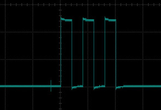
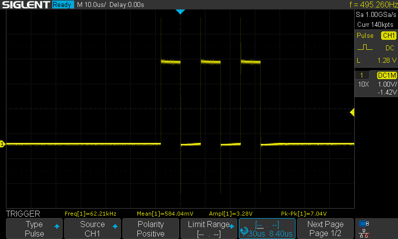
The following sketch generates every 1 second the LED pattern seen in the above image.
Add code so you can: trigger your scope so you can see the same image, copy it and show us your screen capture.
//*********************************************************************************
// Atmega328/UNO
// =============
// Note:
// PIND D0 to D7
// D0=0x01 D1=0x02 D2=0x04 D3=0x08 D4=0x10 D5=0x20 D6=0x40 D7=0x80
// PIND0   PIND1   PIND2   PIND3   PIND4   PIND5   PIND6   PIND7
//
// PINB D8 to D13
// D8=0x01 D9=0x02 D10=0x04 D11=0x08 D12=0x10 D13=0x20
// PINB0   PINB1   PINB2    PINB3    PINB4    PINB5

// PINC D14 to D19
// D14=0x01 D15=0x02 D16=0x04 D17=0x08 D18=0x10 D19=0x20
// PINC0    PINC1    PINC2    PINC3    PINC4    PINC5
//
//*********************************************************************************

//62.5ns delay
#define NOOP           asm("nop\n")

#define PULSE13        PINB = bit(PINB5); PINB = bit(PINB5)

#define                diagnostics

#ifdef diagnostics
#define PULSE63_13     cli(); PINB = bit(PINB5); PINB = bit(PINB5); sei()
#define PULSE126_13    cli(); PINB = bit(PINB5); NOOP; PINB = bit(PINB5); sei()
#define PULSE189_13    cli(); PINB = bit(PINB5); NOOP; NOOP; PINB = bit(PINB5); sei()
#define PULSE252_13    cli(); PINB = bit(PINB5); NOOP; NOOP; NOOP; PINB = bit(PINB5); sei()
#define PULSE315_13    cli(); PINB = bit(PINB5); NOOP; NOOP; NOOP; NOOP; PINB = bit(PINB5); sei()
#define PULSE378_13    cli(); PINB = bit(PINB5); NOOP; NOOP; NOOP; NOOP; NOOP; PINB = bit(PINB5); sei()
#else
#define PULSE63_13     //Not defined
#define PULSE126_13    //Not defined
#define PULSE189_13    //Not defined
#define PULSE252_13    //Not defined
#define PULSE315_13    //Not defined
#define PULSE378_13    //Not defined
#endif

//*******************************************************************************
#define CLOSED            LOW
#define OPEN              HIGH

#define ENABLED           true
#define DISABLED          false

const byte pulsePin     = 13;
const byte LED          = 2;

unsigned long ledMillis;
unsigned long patternMillis;

//*******************************************************************************
void setup()
{
  pinMode(pulsePin, OUTPUT);
  pinMode(LED, OUTPUT);

} //END of setup()

//*******************************************************************************
void loop()
{
  //************************************
  //is it time to toggle the heartbeat LED (every 1ms) ?
  if (micros() - ledMillis >= 1000)
  {
    //restart this TIMER
    ledMillis = micros();

    digitalWrite(LED, !digitalRead(LED));
  }

  //************************************
  //is it time to create the pattern on the LED (every 1 second) ?
   if (millis() - patternMillis >= 1000ul)
  {
    //restart this TIMER
    patternMillis = millis();

    byte currenState = digitalRead(LED);

    //is the LED currently OFF ?
    if (currenState == LOW)
    {
      //create the LED sequence
      for (byte x = 0; x < 6; x++)
      {
        digitalWrite(LED, !digitalRead(LED));
      }
    }

    digitalWrite(LED, currenState);

  }

  //***************************************
  //other none blocking code goes here
  //***************************************

} //END of   loop()
Correction
"do the maths" ![]()
Many oscilloscopes these days have a USB socket at the back. This allows access to both the controls on the front panel and the maths functions and measurements that are displayed on the front panel.
The key to using this on my scope (A Rigol DS1074Z) and many others is the Visa Library.
The main use for this is for making test rigs for factory testing of mass produced items. So any measurement may be made and the results calculated and more importantly recorded for later use. These test rigs might involve many oscilloscopes and other advanced instrument like spectrum analysers, network analysers, programmable power supplies, and signal generators.
The main aim on a production line is to keep the tests as short as possible. Connection to the PCBs are made through what is called a "bed of nails" but in fact these nails are probes with internal springs so they apply pressure on circular test pads on the PCB. A common word for these is "pogo pins".
Test points are applied on every node of the PCB and this allows measurements of components to see if the right ones have been used on the PCB, as well as if they function as expected.
To give you a bit of an idea of what instrument programming is about I include this code I wrote in Python a few years back. It controls the signal generator part of my scope to provide a frequency sweep. I had to use Python because there was a convenient Visa framework I could use.
Anyway more out of curiosity than anything else have a look at this:-
#!/usr/bin/python

"""
Make a Rigol DS1074Z-S oscilloscope produce a frequency sweep
By Mike Cook April 2014
"""

import numpy
import time
import matplotlib.pyplot as plot
import sys
from pyvisa.vpp43 import visa_library
visa_library.load_library("/Library/Frameworks/Visa.framework/VISA")
import visa

fValues = [1.0, 1.2, 1.4, 1.6, 1.8, 2.0, 2.3, 2.6, 3.0, 3.5, 4.0,
           5.0, 6.0, 7.0, 8.0, 9.0]
maxFn = 16 # number of frequencies in a decade

print "Rigol DS1074Z-S sweep and measurement"
# Get the USB device
instruments = visa.get_instruments_list()
usb = filter(lambda x: 'USB' in x, instruments)
print "Scope ",usb
if len(usb) != 1:
    print "Can't find scope", instruments
    sys.exit(-1)
scope = visa.instrument(usb[0], timeout=20, chunk_size=1024000) # bigger timeout for long mem

def main():
   initGen()
   sweep(2,20000)
   scope.write(":KEY:FORCE")
   scope.close()

def sweep(dec, lim) : # starting decade finishing frequency
   f = 0
   freq = 0
   while freq < lim : # 20KHz limit
        freq = fValues[f] * (10**dec)
        #print freq
        setFreq(int(freq))
        f += 1
        if f >= maxFn :
            f = 0
            dec += 1 # next decade
        time.sleep(1.1)


def setFreq(f):
    scope.write(":SOUR1:FREQ:FIX "+str(f))

def initGen():
    scope.write(":SOUR1:OUTPUT1:STATE ON") # enable output
    scope.write(":SOUR1:OUT1:IMP FIFT")  # low impedance output
    scope.write(":SOUR1:FUNC:SHAP SIN")  # Sin wave
    scope.write(":SOUR1:VOLT:LEV:IMM:AMP 2") # output voltage 2V
    scope.write(":SOUR1:MOD:STAT OFF")  # turn off modulation


if __name__ == '__main__':
    main()
My idea was to make a system that could display on the screen a the transfer function of a filter. But I never finished it. If you have not seen Python before the important thing to remember is while C used curly braces { } to define the scope of things like for loops, Python uses indentation to define these things.
See if you can find a Programmer's Guide for your scope.
The introduction in my scope's Programmers Guide says:-
Main Topics in this Manual:
Chapter 1 Programming Overview
This chapter introduces how to build the remote communication between DS1000Z series digital oscilloscope and the PC. It also introduces the remote control method and the SCPI commands.
Chapter 2 Command System
This chapter introduces the syntax, function, parameter and using instruction of each command.
Chapter 3 Programming Demos
This chapter lists some programming demos to illustrate how to use commands to realize the common functions of the oscilloscope in the development environments of Excel, LabVIEW, Matlab, Visual Basic 6.0 and Visual C++ 6.0.
@kgray9,
In addition to everything others have suggested (and my apologies if this has been suggested and I missed it) when you send the pulse down a coax or twisted pair see what happens to the pulse on the oscilloscope with the far end shorted and open circuit. When you have done that try different resistor values across the wires.
Ahha! I got it.
The pulses are 7.8us wide at the peak, so I set the trigger for pulse, and set the lower and upper time around that. You can sometimes see the edge of a 1ms pulse on the edge of the screen.
Thanks for all the info @Grumpy_Mike. Thats so cool that you control control an o'scope with python! My scope has a USB port on the back, but the app for it is for windows, and I have a Mac ![]() .
.
I have done some Python programming on Raspberry Pis, not much though.
Hello @PerryBebbington!
I dont think anyone suggested that yet. Ill try that out!
![]()
You are have too much fun ![]()
    if (currenState == LOW)
    {

      PULSE63_13;  //  <———<<<<  add this line

      //create the LED sequence
      for (byte x = 0; x < 6; x++)
      {
        digitalWrite(LED, !digitalRead(LED));
      }
    }
In the below sketch line PULSE63_13; was added; place channel 1 on Arduino pin 13, set your trigger for channel 1.
Probe 2 goes on LED pin.
//*********************************************************************************
// Atmega328/UNO
// =============
// Note:
// PIND D0 to D7
// D0=0x01 D1=0x02 D2=0x04 D3=0x08 D4=0x10 D5=0x20 D6=0x40 D7=0x80
// PIND0   PIND1   PIND2   PIND3   PIND4   PIND5   PIND6   PIND7
//
// PINB D8 to D13
// D8=0x01 D9=0x02 D10=0x04 D11=0x08 D12=0x10 D13=0x20
// PINB0   PINB1   PINB2    PINB3    PINB4    PINB5

// PINC D14 to D19
// D14=0x01 D15=0x02 D16=0x04 D17=0x08 D18=0x10 D19=0x20
// PINC0    PINC1    PINC2    PINC3    PINC4    PINC5
//
//*********************************************************************************

//62.5ns delay
#define NOOP           asm("nop\n")

#define PULSE13        PINB = bit(PINB5); PINB = bit(PINB5)

#define                diagnostics

#ifdef diagnostics
#define PULSE63_13     cli(); PINB = bit(PINB5); PINB = bit(PINB5); sei()
#define PULSE126_13    cli(); PINB = bit(PINB5); NOOP; PINB = bit(PINB5); sei()
#define PULSE189_13    cli(); PINB = bit(PINB5); NOOP; NOOP; PINB = bit(PINB5); sei()
#define PULSE252_13    cli(); PINB = bit(PINB5); NOOP; NOOP; NOOP; PINB = bit(PINB5); sei()
#define PULSE315_13    cli(); PINB = bit(PINB5); NOOP; NOOP; NOOP; NOOP; PINB = bit(PINB5); sei()
#define PULSE378_13    cli(); PINB = bit(PINB5); NOOP; NOOP; NOOP; NOOP; NOOP; PINB = bit(PINB5); sei()
#else
#define PULSE63_13     //Not defined
#define PULSE126_13    //Not defined
#define PULSE189_13    //Not defined
#define PULSE252_13    //Not defined
#define PULSE315_13    //Not defined
#define PULSE378_13    //Not defined
#endif

//*******************************************************************************
#define CLOSED            LOW
#define OPEN              HIGH

#define ENABLED           true
#define DISABLED          false

const byte pulsePin     = 13;
const byte LED          = 2;

unsigned long ledMillis;
unsigned long patternMillis;

//*******************************************************************************
void setup()
{
  pinMode(pulsePin, OUTPUT);
  pinMode(LED, OUTPUT);

} //END of setup()

//*******************************************************************************
void loop()
{
  //************************************
  //is it time to toggle the heartbeat LED (every 1ms) ?
  if (micros() - ledMillis >= 1000)
  {
    //restart this TIMER
    ledMillis = micros();

    digitalWrite(LED, !digitalRead(LED));
  }

  //************************************
  //is it time to create the pattern on the LED (every 1 second) ?
   if (millis() - patternMillis >= 1000ul)
  {
    //restart this TIMER
    patternMillis = millis();

    byte currenState = digitalRead(LED);

    //is the LED currently OFF ?
    if (currenState == LOW)
    {

      PULSE63_13;  //  <———<<<<  add this line

      //create the LED sequence
      for (byte x = 0; x < 6; x++)
      {
        digitalWrite(LED, !digitalRead(LED));
      }
    }

    digitalWrite(LED, currenState);

  }

  //***************************************
  //other none blocking code goes here
  //***************************************

} //END of   loop()
I think one of the Youtube videos says to adjust a load resistor (potentiometer, to ~ 50 ohms) to get no reflection.
I think I have to wait for NI-VISA to update to MacOS 13 but I definitely want to play with programming my Rigol.
Got you again ![]() :
:
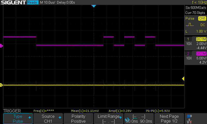
Trigger is set to pulse on channel 1 (pin D13) with a time range of 50ns to 90ns (63ns pulse). It works!
Thanks @LarryD . Ill take some more! Give me a hard one ![]()
A programmer is writing a game.
You need to capture (10 times) a LED's ON state by pushing a switch.
When the LED on D2 lights, the user pushes a switch connected to D8.
If the switch is pressed while the LED is ON, Success is printed on the serial monitor.
If the switch is pressed too soon or too late, the serial monitor prints: LED was not ON ![]()
After succeeding 10 times, the game restarts and you again have 10 tries.
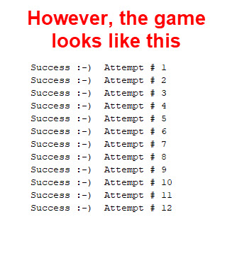
Catching the LED 10 times does not restart the game ![]() .
.
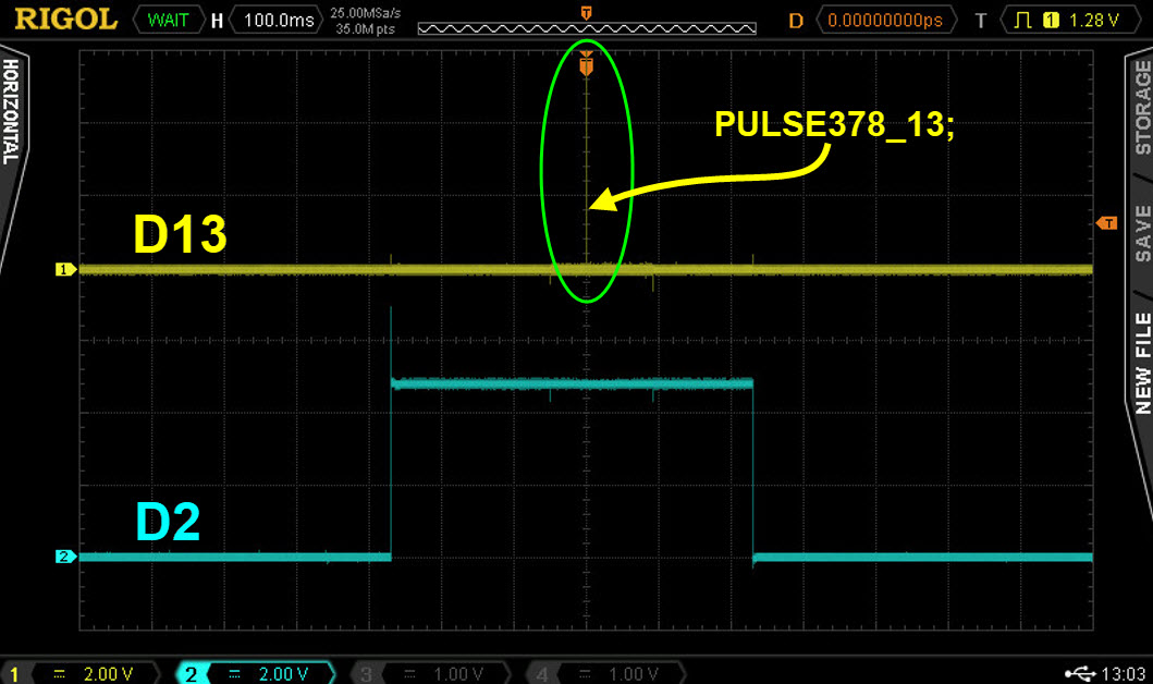
The programmer adds PULSE378_13; a scope trigger, to see if the LED is on when the switch is pushed.
Here we see the LED was ON, blue trace, when the switch was pressed, i.e. when the trigger is seen on the scope, Yellow trace.
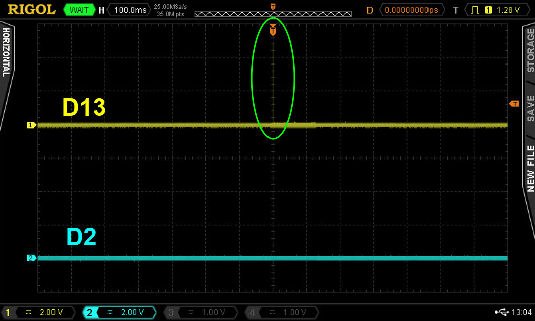
Here we see the user was too late in pushing the switch:
Here the user pushed the switch when the LED was not ON.
This is what should be printed:

This is what is printed printed:
Here is the sketch:
//*********************************************************************************
// Atmega328/UNO
// =============
// Note:
// PIND D0 to D7
// D0=0x01 D1=0x02 D2=0x04 D3=0x08 D4=0x10 D5=0x20 D6=0x40 D7=0x80
// PIND0   PIND1   PIND2   PIND3   PIND4   PIND5   PIND6   PIND7
//
// PINB D8 to D13
// D8=0x01 D9=0x02 D10=0x04 D11=0x08 D12=0x10 D13=0x20
// PINB0   PINB1   PINB2    PINB3    PINB4    PINB5

// PINC D14 to D19
// D14=0x01 D15=0x02 D16=0x04 D17=0x08 D18=0x10 D19=0x20
// PINC0    PINC1    PINC2    PINC3    PINC4    PINC5
//
//*********************************************************************************

//62.5ns delay
#define NOOP           asm("nop\n")
#define PULSE13        PINB = bit(PINB5); PINB = bit(PINB5)

#define                diagnostics

#ifdef diagnostics
#define PULSE63_13     cli(); PINB = bit(PINB5); PINB = bit(PINB5); sei()
#define PULSE126_13    cli(); PINB = bit(PINB5); NOOP; PINB = bit(PINB5); sei()
#define PULSE189_13    cli(); PINB = bit(PINB5); NOOP; NOOP; PINB = bit(PINB5); sei()
#define PULSE252_13    cli(); PINB = bit(PINB5); NOOP; NOOP; NOOP; PINB = bit(PINB5); sei()
#define PULSE315_13    cli(); PINB = bit(PINB5); NOOP; NOOP; NOOP; NOOP; PINB = bit(PINB5); sei()
#define PULSE378_13    cli(); PINB = bit(PINB5); NOOP; NOOP; NOOP; NOOP; NOOP; PINB = bit(PINB5); sei()

#else
#define PULSE63_13     //Not defined
#define PULSE126_13    //Not defined
#define PULSE189_13    //Not defined
#define PULSE252_13    //Not defined
#define PULSE315_13    //Not defined
#define PULSE378_13    //Not defined
#endif

//*******************************************************************************
#define PUSHED                    LOW
#define notPUSHED                 HIGH

#define LEDoff                    LOW
#define LEDon                     HIGH

#define ENABLED                   true
#define DISABLED                  false

const byte triggerPin           = 13;
const byte heartbeatLED         = 12;
const byte LED                  = 2;
const byte mySwitch             = 8;
const byte startValue           = 9;          //0 thru 9 gives user 10 attempts in each game
byte attemptNumber              = 1;
byte lastMySwitchState          = notPUSHED;
byte LEDstate                   = LEDoff;
byte counter                    = startValue;
const unsigned long onTime      = 500;        //500 milli seconds
unsigned long heartbeatMillis;
unsigned long switchMillis;
unsigned long ledMillis;
unsigned long gameMillis;
unsigned long offMillis;


//*******************************************************************************
void setup()
{
  Serial.begin(9600);

  pinMode(triggerPin, OUTPUT);
  pinMode(heartbeatLED, OUTPUT);

  pinMode(LED, OUTPUT);
  digitalWrite(LED, LEDoff);
  LEDstate = LEDoff;

  pinMode(mySwitch, INPUT_PULLUP);

} //END of setup()

//*******************************************************************************
void loop()
{
  //************************************           heartbeat  T I M E R
  //time to toggle the heartbeat LED ?
  if (millis() - heartbeatMillis >= 500)
  {
    //restart the TIMER
    heartbeatMillis = millis();

    //toggle LED
    digitalWrite(heartbeatLED, !digitalRead(heartbeatLED));

  }

  //************************************           check switches  T I M E R
  //time to check the switches ?
  if (millis() - switchMillis >= 50)
  {
    //restart the TIMER
    switchMillis = millis();

    checkSwitches();

  }

  //************************************           LED ON  T I M E R
  //is it time to turn on the LED
  if (millis() - gameMillis >= random(5000, 10000))
  {
    //restart this TIMER
    gameMillis = millis();

    LEDstate = LEDon;
    digitalWrite(LED, LEDstate);

    //restart the OFF TIMER
    offMillis = millis();

  }

  //************************************           LED OFF  T I M E R
  //if the LED is ON, is it time to turn it OFF ?
  if (LEDstate == LEDon && millis() - offMillis >= onTime)
  {
    LEDstate = LEDoff;
    digitalWrite(LED, LEDstate);

  }

  //***************************************
  //other none blocking code goes here
  //***************************************

} //END of   loop()


//*******************************************************************************
void checkSwitches()
{
  byte inputState;

  //************************************                  m y S w i t c h
  inputState = digitalRead(mySwitch);

  //was there a change in state
  if (lastMySwitchState != inputState)
  {
    //update to the new state
    lastMySwitchState = inputState;

    //is the switch pushed ?
    if (inputState == PUSHED)
    {
      PULSE378_13;      //  <--------<<<<<  Generate our 378ns trigger pulse

      //is the LED ON
      if (LEDstate == LEDon)
      {
        //the switch was pushed at the correct time
        counter--;

        Serial.print("Success :-)  Attempt # ");
        Serial.println(attemptNumber++);

        //is the game finished ?
        if (counter < 0)
        {
          Serial.println("You have finished the game.");

          //initialize things for a new game
          attemptNumber = 1;
          counter = startValue;

          Serial.println("New game started.");
        }
      }

      //the LED was OFF when the switch was pushed
      else
      {
        Serial.print("LED was not ON :-(   Attempt # ");
        Serial.println(attemptNumber++);
      }

    }

  } //END of   mySwitch code

} //END of   checkSwitches()
How long does it take the following function to execute ?
checkSwitches();
Ahha!
The counter variable is a byte, so it never goes negative. Instead of going negative, it goes to 255 and continues to count down from there. if (counter < 0) is waiting for the byte variable to go negative but it doesn't! Instead do if (counter == 0) and add 1 to the counter variable during the definition.
Also, the checkSwitches(); function takes 4.3us to execute once as seen below (without the button being pressed):
Is that correct?
Awesome!
That was the other option.
Do you have any more? Sorry, not trying to be a bother. lol, this thread could almost be referred to as an oscilloscope test.
Thanks again @LarryD !
After supper ![]()
A programmer is generating a 10 hertz clock on pin D12.
There seems to be a problem when the clock first starts up, however, after a short period of time, the clock is perfect ![]()
const byte clockLED             = 12;

bool greetingFlag               = false;

unsigned long clockMillis;

const unsigned long interval    = 50;  //50ms

//*********************************************************************************
void setup()
{
  Serial.begin(9600);

  pinMode(clockLED, OUTPUT);

} //END of   setup()


//*********************************************************************************
void loop()
{
  //******************************************
  //print a greeting at the begining for the sketch
  if (greetingFlag == false)
  {
    //print a greeting to the user
    Serial.println("Welcome to Oscilloscope Training.");

    //give 2 seconds to read the serial monitor
    delay(2000);

    //we have finished with the greeting, disable it form here on in
    greetingFlag = true;
  }

  //******************************************
  //toggle the clock LED every 50ms
  if (millis() - clockMillis >= interval)
  {
    //restart the TIMER
    clockMillis = clockMillis + interval;

    //toggle LED
    digitalWrite(clockLED, !digitalRead(clockLED));
  }

} //END of    loop()
That would be because there is a delay(2000); in the if (greetingFlag == false) function. This delays the clock from starting by 2000ms. Also the serial display keeps the data displayed on it, so you wouldn't need to wait 2 seconds at all ![]() .
.
In addition, it takes 2.7us for void loop() to run once ![]() .
.
Correct?
Edit:
9.92(10.02) hertz pulse: