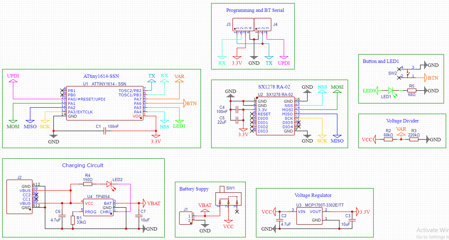
Hi! I want to make a custom PCB for one of my projects, it involves a LoRa Ra-02 RF 433MHz module sending a signal at a press of a button, I would usually need to send a signal once an hour, then the module will be powered off, so very low consumption so I decided to use a 50mAh 3.7V 1S LiPo battery. The battery wires will be soldered on pads on the PCB, the ATtiny1614 MCU will be programmed on one of those SOP to DIP adapters on a breadboard. This is a continuation of this post, I made some adjustments and I added a TP4054 charging controller in order to charge the battery at 30mA. The distance between tracks on the PCB will be minimum 0.762mm between the edges of SMD pads and THT pads, or between edge of track to pad or between tracks, the track width will be 0.254mm. I have question about the capacitors, and if the values are right for the MCP1700, Ra-02 and the TP4054 components, I followed the datasheets for the MCP1700 and the TP4054 but they seem kind off odd to me, higher capacitance for charging circuit and smaller one for voltage regulator, as for the Ra-02 module I didn't find and values in a datasheet and I copied them from a schematic. Also for a PCB containing an RF module that will use an external antenna(in my case) what type of components are better, SMD or THT? I tried to use only SMD components. Can I route GND and live tracks under the module? What considerations for VIAs? I hope my schematic is overall correct...Thank you!

Can you clarify what you mean by that, its not clear ?
For instance - The external antenna is the case ?
Are you really short on space ?
I meant that in my case I will use an external antenna.
All of that seems irrelevant when all the RF signals are in/on the RF module. Be aware the your antenna needs to be mounted on a metal case with a coax cable connecting to the module connector.
Is the metal case mandatory, what's it for? On the first prototype I mounted the antenna on a plastic wall(the case for the modules was 3D printed) and I would want to do the same for this PCB.
If you care about distance and consistent reception of that signal, ask Google to show you about "ground plane antenna", because that is what your device is designed for.
So from what I understand, I will screw the antenna connector on the plastic wall, but between it and the plastic I place a copper plate let's say , 30x15x1mm and then solder a wire to that plate and connect it to a GND pin on the PCB?
Are you going to extend from the unit's coax connector to the antenna coax connector with a pig-tail of coax cable with connectors on each end? If so, then the outer shield of the coax and the connectors are ALL connected to the unit ground.
Or are going to mount the Ra-02 on the plastic with a hole in the plastic so the antenna's connector can mate to the Ra-02 connector? If so, then the shield and the circuit board of the Ra-02 become the ground plane and nothing else needs to be added. Same configuration as your previous testing.
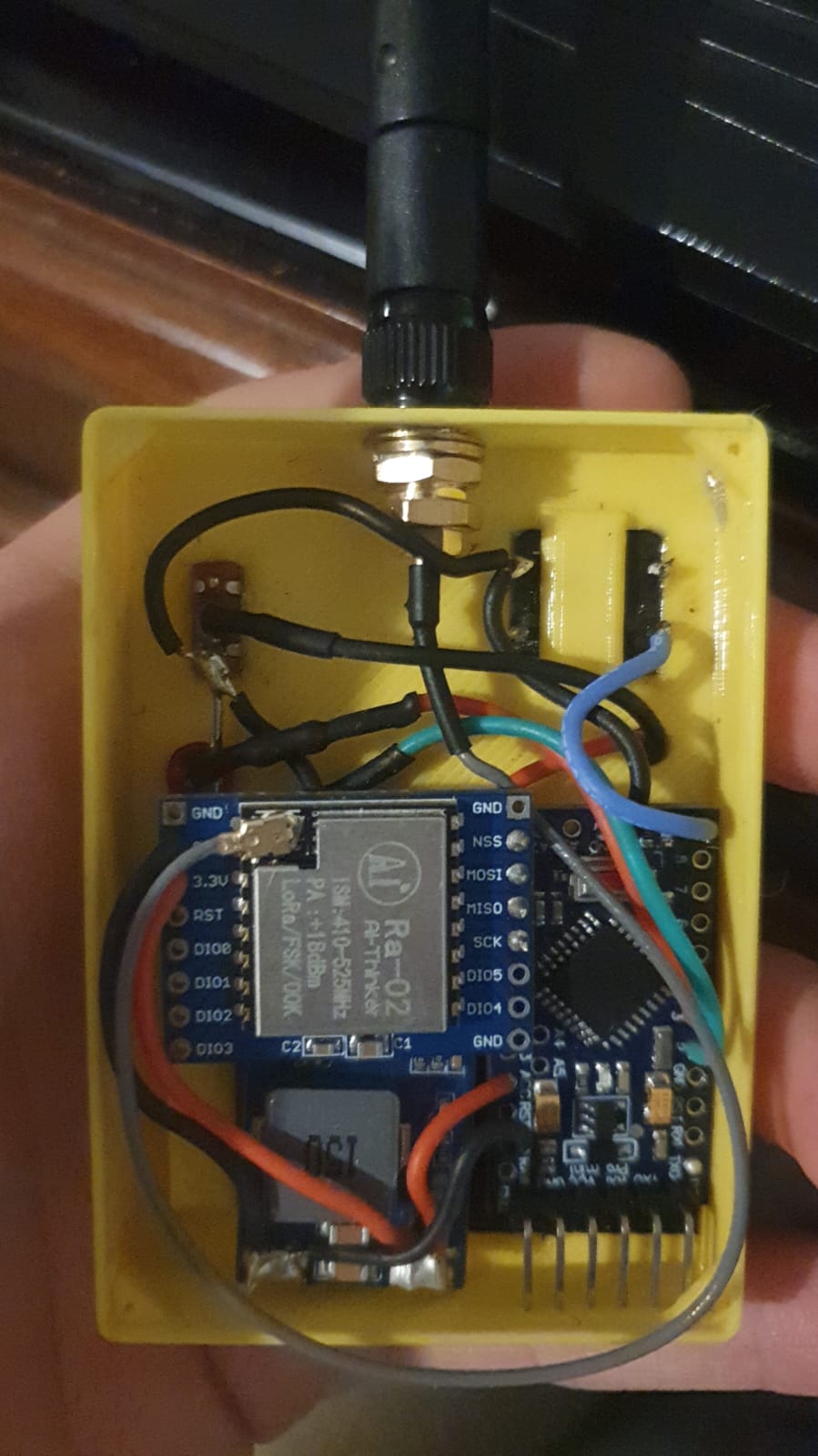
Ah, the picture explains more than the Amazon link shows. The connector at the end of the coax, where it goes through the plastic needs to have the metal ground plane right there. Make a matching hole in the ground plane and let the coax connector hold it to the plastic. Either side of the plastic will work. The coax shield is the only ground connection needed.
Do you mean the grey wire? It doesn't look like coax to me.
Warning! I'm not an RF expert.
It's coax. Doesn't have a military RG identification.
Would a ground plane on the PCB, directly under the LoRa module add some benefits?
No, Only when it is part of the antenna. The vertical part of your antenna is 1/4 wavelength long. To be resonant, it needs to be 1/2 wavelength long. The ground plane supplies the missing 1/4 wavelength. It could also be 4 or or 8 or 16 wires spread out, but solid is so much easier to work with!
How big should the ground plane for the antenna be?
1/4 wavelength from the center of the hole where the coax connector goes through.
Would an antenna connector soldered on the PCB benefit me? If I want to add one, do I need to control the impedance of the entire PCB or only the trace that is connected to the antenna pin of the module and the antenna connector? What calculator to use for impedance?
So many questions in a single post makes me wonder why you are not willing to experiment to find the answers?
The impedance of the RF generator needs to match the impedance of the radiator. Otherwise RF will be reflected back to the generator and will not be radiated. Unless the RF is radiated, it is of no use for communication.
There is a vast array of software that engineers use to develop circuits, but is way beyond my education level. Much of it is costly, but some with limited capability is free. Do some research for yourself!