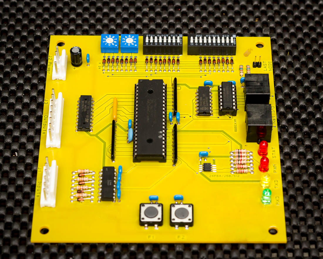
Hey Everyone, I have an interesting project I am working on. I have a stand alone gaming video slot machine (like you see in gas stations) that is equipped with a remote accounting system. This system has a control station that sits on your checkout counter and it has a small board that is inside the game machine. The control station and the machine board are connected by a standard cat 5 cable. I am attempting to hack and interpret the messages between the two devices. My plan is to design a new board with allot more features to replace the board that is inside the game machine. I want this new device to be compatible with the base station that is already in place. On the board that is inside the game machine (yellow board in pictures) there is a max3080 convertor chip connected to the rj45 terminal leading me to believe that the boards are communicating using rs485 protocol. I used 2 rj45 breakouts and a rs485 to serial converter on a breadboard. The arduino is reading any rs485 data from the convertor and outputting to the serial monitor. I have been using the inputs from the rs485 converter to "Probe" the different lines on the rs485 breakout in various combinations. I am getting input but it just seems to be random numbers. Any help would be greatly appreciated.
Here is my code
//COM 3 Slave

/* YourDuino SoftwareSerialExample1Remote
   - Used with YD_SoftwareSerialExampleRS485_1 on another Arduino
   - Remote: Receive data, loop it back...
   - Connect this unit Pins 10, 11, Gnd
   - To other unit Pins 11,10, Gnd  (Cross over)
   - Pin 3 used for RS485 direction control
   - Pin 13 LED blinks when data is received

   Questions: terry@yourduino.com
*/

/*-----( Import needed libraries )-----*/
#include <SoftwareSerial.h>
/*-----( Declare Constants and Pin Numbers )-----*/
#define SSerialRX        10  //Serial Receive pin
#define SSerialTX        11  //Serial Transmit pin

#define SSerialTxControl 3   //RS485 Direction control
#define RS485Transmit    HIGH
#define RS485Receive     LOW

#define Pin13LED         13

/*-----( Declare objects )-----*/
SoftwareSerial RS485Serial(SSerialRX, SSerialTX); // RX, TX

/*-----( Declare Variables )-----*/
int byteReceived;
int byteSend;

void setup()   /****** SETUP: RUNS ONCE ******/
{
  // Start the built-in serial port, probably to Serial Monitor
  Serial.begin(9600);
  Serial.println("SerialRemote");  // Can be ignored

  pinMode(Pin13LED, OUTPUT);
  pinMode(SSerialTxControl, OUTPUT);

  digitalWrite(SSerialTxControl, RS485Receive);  // Init Transceiver

  // Start the software serial port, to another device
  RS485Serial.begin(4800);   // set the data rate
}//--(end setup )---


void loop()   /****** LOOP: RUNS CONSTANTLY ******/
{
  //Copy input data to output
  if (RS485Serial.available())
  {
    byteSend = RS485Serial.read();   // Read the byte

    digitalWrite(Pin13LED, HIGH);  // Show activity
    delay(10);
    digitalWrite(Pin13LED, LOW);

    //digitalWrite(SSerialTxControl, RS485Transmit);  // Enable RS485 Transmit
    //RS485Serial.write(byteSend); // Send the byte back
    Serial.println(byteSend);
    delay(10);
    digitalWrite(SSerialTxControl, RS485Receive);  // Disable RS485 Transmit
//    delay(100);
  }// End If RS485SerialAvailable

}//--(end main loop )---

/*-----( Declare User-written Functions )-----*/
//NONE

//*********( THE END )***********
Below is an example of the Serial monitor output:
52
254
83
52
169
55
239
87
229
125
251
248
239
213
250
248
239
125
250
248
86
135
251
248
85
227
251
248
84
239
239
248
85
85
84
248
84
84
193
248
87
87
86
86
101
86
87
87
101
87
86
86
248
86
HEEELP