I bought a bag of 2N222 transistors more than 5 years ago but didn't use them then. Now that I'm using Arduino I got them out. I have been having problems with them. I tried a simple circuit from a video today with a couple of them. If they worked they were very erratic, the blink rate kept changing and the rate seemed too fast for the capacitor I was using. Could it be I have a bad batch?
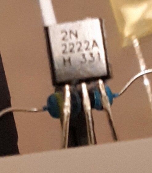
I bought a 100 count pack of 2N2222 from Amazon a few years ago. They are clearly marked 2N2222, see below. They are actually P2N2222. Pins C and E are swapped. I guess that's why i got them so cheap
I doubt that 0.25% difference in BE or BC diode drop is a reliable indicator.
That drop is also temp dependent, and likely transistor type dependent.
60 years ago finding the base with a multimeter was a common test. I didn't have any other tester.
To find the collector I connected the meter to collector and emitter, and connected the base with a wet finger to the red lead. It was correct when there was some meter movement.
This was the time you made a power amplifier with an AC187/AC188 pair
Leo..
Hi,
The circuit work because of the 2N2222 reverse bias Emitter Base voltage, Vebo, being only 6V.
The Base Collector is in this circuit forward biased, so conducts all the time.
The power supply charges the electro capacitor up, when the voltage on the capacitor reaches the voltage == (the base emitter reverse bias voltage)+( the forward drop collector to base)
The base-emitter junction breaks over and conducts.
The capacitor discharges through the transistor and the LED.
As the charging current is much lover than the discharge current, the voltage on the capacitor will decrease and the base-emitter will cease conduction and then allow the capacitor to charge back up.
I hope that is clear, not enough caffeine in the coffee stream today.
Tom..
PS. Tweaking the resistor and capacitor values will help to get good operation.
As I recall, Vebo means voltage between emitter and base with the collector open, the collector is not connected and the reversed emitter - base junction acts as a zener diode.
Your image of the transistor is what mine looks like, it's too small to get an image of. I turned it both was in the circuit and it lights up but doesn't blink.
I am using a 9v power supply right now with a 2k resistor and the circuit with a BC547 is working fine.