Well, I actually got one of the new 2N2222s to work. But it's really weird how it's doing it. Quoting myself,
Tonight when I was just trying the new 2N22s they would light up a like before but not blink. But then suddenly it did for a short time so I kept messing with it. I found that if I touch the wire between the cathode of the LED and the closest side of the 330ohm resister it will blink.
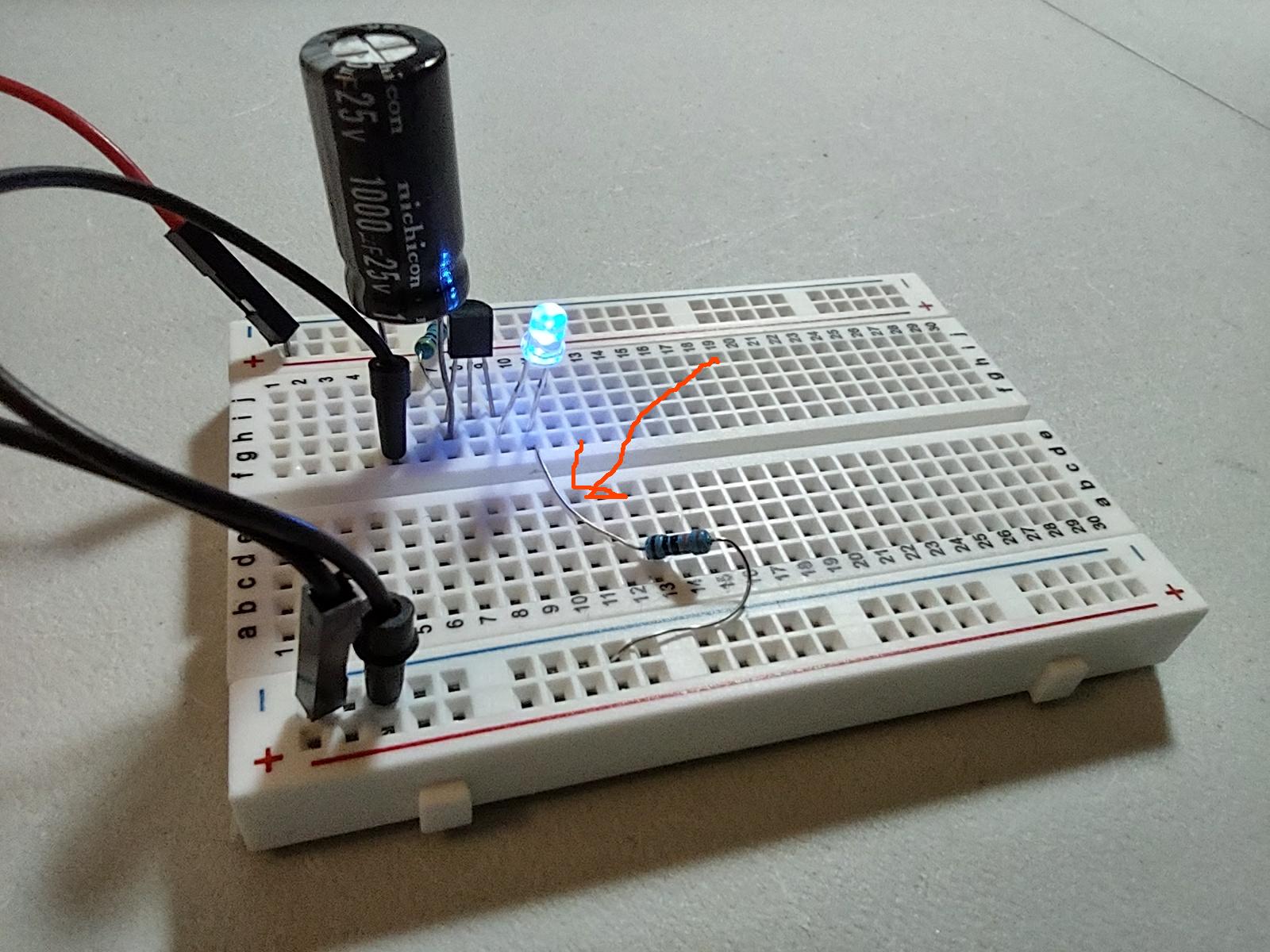
Here are some images. I took a video of me touching the wire but I can't seem to upload it. Where the red arrow is on the third image is where I touch and it blinks.
The 2N2222 have not been made for perhaps 40 years or more. Like all solid state devices, they were made by the10's of millions and then never made again. To set up a production line costs millions and new type stuff is always made, also in the 10' of millions.
2n2222 is npn bjt. As per mentioned circuit emitter is connected to +vcc ( arrow pointing out )and collector to ground. Diode cathode is connected to gnd via resistor which is ok but as per bjt arrow in schematic diode is reverse biased and cant pass any current thru it. Besides that base is not connected to anything
What I gather from this is: With enough voltage applied, the reverse biased base - emitter junction will conduct (as a zener diode would) and simulate a flow of base current and then a current can flow backwards between emitter and collector (as a PNP transistor). that can light the LED and discharge the capacitor to below the conduction voltage, thus forming a relaxation oscillator. Very interesting!
A company called Microsemi still manufacture the 2n2222 and its complement the 2n2907 in SMD and TO-18 packages. They are too expensive to consider($3-$6) unless you are repairing military hardware or some such though.
Fastlad and circuitlab simulation with 2n2222 doesnt prove that this can work. Actually its exact opposite this circuit can work only if collector and emitter are shorted internally in bjt. Can someone make this corcuit work in simulator? Even in its at vebo breakdown all the time it doesnt mean that this is right way to make a flasher. Same way we can make a heater from almost any ic :-)))))
That is a typical circuit for a unijunction transistor oscillator, but I do not see how a reversed NPN can work, even if some say it does. Not that I doubt it, since I haven't tried it. I just cannot explain it.
Funny. Been using 2N2222s for 40 years and never encountered this issue.
I have had the P2N2222 pinout swap but was able to correct it by reversing it.
I know 25% difference in B-E, and B-C drop doesn't seem like much and actually, it doesn't seem anything close to 25% but it has always been enough to tell what the pinout was since the one with the higher drop is the emitter. I suppose mislabeled components isn't unheard of but it would seem one should be able to determine the pinout without any label by using a DMM (on diode scale: red lead to base, black to emitter as shown here
**. That's just my take on it.