Hi,
I just hooked pin 15 of my JHD 162A ([u]Chinese datasheet[/u]) to a PWM output on the Arduino (pin 3) to be able to set and change the brightness of the backlight.
It works well, even if the maximum light level obtained when analogWrite(3,255) is less than when it was hooked directly to +5 (which doesn't matter to me).
The question is, won't it damage the Arduino or the LCD in the long run ? Is there a safest way to do the connection (I'm no EE, so don't be shy to include details in your answer) ? Shouldn't I at least put a resistor between the two (which value) ?
Ah, I think you should stop immediately and add a resistor (maybe 150 Ohm) between Arduino pin and back light. Running without a resistor will eventually damage either the arduino pin or the back light, whichever is weaker.
The diagram is showing a resistor between LED+ and VCC.
(1) The 14-pin HD44780 LCD interface and the 2-pin Backlight are two completely (electrically) unrelated systems. The HD44780 was around at for least a decade before LED backlights became popular. There were some devices with electroluminescent backlights that required something in the neighborhood of 100 v to operate, but they were not common either.
Even with the incorrect title most people understand what you mean, I just don't think the misconception about a '16-pin interface' as used in some of the Arduino documentation should be encouraged.
(2) There are no standards concerning the LED backlights. They have varying numbers of LEDs in varying series and/or parallel combinations. Some implementations require an external series resistor and others do not since they have the required resistance already on the board.
A series resistance will never hurt anything and it is a essential to use one if you are not sure about your backlight configuration. Since there are frequently several parallel strings of LEDs you may need a much smaller value than 150 ohms.
I don't like this particular back light for Arduino projects. To regulate its brightness finely, you need very small resistors and there's not a lot of choices among standard resistance values within that range.
Yeah, 150 Ohm is overkill, but it may be enough to help the user see the text in complete darkness, which is much less bright than what most people want, having back light visible and glowing in well-lit rooms.
Thank you so much for all your answers. I did not fry the arduino or any LCD I tried (3 differents), but I feel lucky after reading the thread
I'll try a 150 ohm resistor and decrease the value a bit if it's really unreadable at full PWM.
I'm back, trying to get more power to the dimmest LCDs.
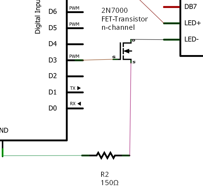
The 150 ohm resistor in serial with the pwm works nicely, but I would want to try to use a MOSFET to get more juice to the LCD backlight.
I have a 2N7000 available and wished to use it.
Could you just tell me if this is the right way to do it ?
As I already said, I'm a beginner in electronics and I'm afraid to make some stupid choice which would fry the arduino or the lcd (or both !).
Exactly what I needed, Thank you !
Side note : It seems "Justin Berken" use the wrong symbol on his diagram (p-channel instead of n-channel), but judging from the datasheet of his MOSFET, it's a n-channel as my 2N7000.