Help Calibrating my 3.95" (ILI9488 8-BIT By McuFriend) + microSD

Hi Guys. I hope someone can help me on this.
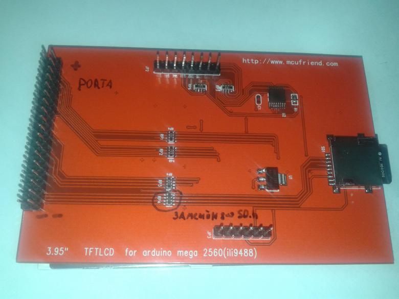
I recently bought a 3.95" TFTLCD for arduino Mega 2560 (ili9488) by MCUFriend. It comes with a XPT2046 for touch control.
Here is the picture.

upload picture without account

Apparently is a 8bit

I could make it work with the following libraries -> libraries СанСаныч от Slider ( UTFT,UTouch,tinyFat,UTFT_tinyFAT,Adafruit_TFTLCD,SD ) 3.95 TFT LCD for arduino mega 2560(ili9488) .rar — Yandex.Disk from this russian forum -> 3.5" TFT LCD красный меговский + mega 2560 R3 . РЕШЕНО ! + как решить другие ! | Аппаратная платформа Arduino

The issue is: I can't calibrate the display properly. Using the "UTouch_Calibration" sketch and replacing new calibration values in UTouchCD.h does not work properly. After calibration, using the UTouch_ButtonTest sketch doesn't work properly either (no matter what precision I use, from LOW to EXTREME). It doesn't makes any difference.

When I first upload the UTouch_Calibration sketch i realised that the Text was rotated 180°, so editing the file "initlcd.h"

in LCD_Write_DATA(0b10001000);

rotated the screen to a properly position.

//case ILI9327_8:

//9488
 delay(500);
LCD_Write_COM(0xE0);
LCD_Write_DATA(0x00);
LCD_Write_DATA(0x07);
LCD_Write_DATA(0x10);
LCD_Write_DATA(0x09);
LCD_Write_DATA(0x17);
LCD_Write_DATA(0x0B);
LCD_Write_DATA(0x40);
LCD_Write_DATA(0x8A);
LCD_Write_DATA(0x4B);
LCD_Write_DATA(0x0A);
LCD_Write_DATA(0x0D);
LCD_Write_DATA(0x0F);
LCD_Write_DATA(0x15);
LCD_Write_DATA(0x16);
LCD_Write_DATA(0x0F);
LCD_Write_COM(0xE1);
LCD_Write_DATA(0x00);
LCD_Write_DATA(0x1A);
LCD_Write_DATA(0x1B);
LCD_Write_DATA(0x02);
LCD_Write_DATA(0x0D);
LCD_Write_DATA(0x05);
LCD_Write_DATA(0x30);
LCD_Write_DATA(0x35);
LCD_Write_DATA(0x43);
LCD_Write_DATA(0x02);
LCD_Write_DATA(0x0A);
LCD_Write_DATA(0x09);
LCD_Write_DATA(0x32);
LCD_Write_DATA(0x36);
LCD_Write_DATA(0x0F); 
LCD_Write_COM(0xB1);
LCD_Write_DATA(0xA0);
LCD_Write_COM(0xB4);
LCD_Write_DATA(0x02);
LCD_Write_COM(0xC0);
LCD_Write_DATA(0x17);
LCD_Write_DATA(0x15);
LCD_Write_COM(0xC1);
LCD_Write_DATA(0x41);
LCD_Write_COM(0xC5);
LCD_Write_DATA(0x00);
LCD_Write_DATA(0x0A);
LCD_Write_DATA(0x80);
LCD_Write_COM(0xB6);
LCD_Write_DATA(0x02);
LCD_Write_COM(0x36);  
LCD_Write_DATA(0b10001000); // было 0x48 0b01001000  , чтобы перевернуть надо  0x88 0b10001000
LCD_Write_COM(0x3a);   
LCD_Write_DATA(0x55); //55-65k  56-262k
LCD_Write_COM(0xE9);
LCD_Write_DATA(0x00); 
LCD_Write_COM(0XF7);
LCD_Write_DATA(0xA9);
LCD_Write_DATA(0x51);
LCD_Write_DATA(0x2C);
LCD_Write_DATA(0x82);
LCD_Write_COM(0x11);
delay(120);
LCD_Write_COM(0x29);
delay(500);
// break;

I need to mention that I tried to calibrate with both screen rotations and the problem remains.

Another issue that I noticed is that when running the UTouch_QuickDraw sketch the drawing is almost imposible, very imprecise and it draws dots all over the screen. I guess that this has to be a calibration issue?

Well, hope someone can help me!
Thanks for your time!

You clearly have an 8-bit interface. There are only 4 resistor-packs.
The photo in the Russian Forum link shows a 16-bit interface. There are 7 resistor-packs.

I have a pcb exactly the same as your Russian Forum link. My Shield contains a RM68140 controller.
My Touch Controller works ok.

I suggest that you compare the pcb traces around your XPT2046 Touch Controller chip. The pin wiring might be different.
Forget about the Calibration for the moment. Just report the RAW x, y values from the XPT2046 to the Serial Terminal. Do they make sense?

David.

Hi David, thanks for your response. I use this steps in that forum, the last reply -> 3.5" TFT LCD красный меговский + mega 2560 R3 . РЕШЕНО ! + как решить другие ! | Аппаратная платформа Arduino

This is the russian forum image:

If you observe, it's almost the same as mine.

About what you said "report the RAW x, y values from the XPT2046 to the Serial Terminal", I don't know how to do that. Can you please help me on this? Thanks!

You are probably using UTouch.h or URTouch.h library from Henning Karlsen (RinkyDink)

Look at the public methods:

 int16_t TP_X ,TP_Y;    //raw values from XPT2046
 int16_t getX();        //pixel value from Calibration.
 int16_t getY();

So you can simply check for dataAvailable() and write the RAW values to the Serial Terminal.

What value is the Resistor-Pack that is connected to the microSD ?
Most are 10k and consequently the SD does not work reliably.

David.

Hi Again!
Well, I did some tests as suggested by David.

Running this sketch:

#include <memorysaver.h>
#include <UTFT.h>
#include <UTouch.h>
#include <UTouchCD.h>
#define TOUCH_ORIENTATION LANDSCAPE

UTFT    myGLCD(31,38,39,40,41);
UTouch  myTouch( 6, 5, 4, 3, 2);

int dispx, dispy;
void setup() {
  Serial.begin(9600);
  myGLCD.InitLCD();
  myGLCD.clrScr();
  myTouch.InitTouch(TOUCH_ORIENTATION);
  dispx=myGLCD.getDisplayXSize();
  dispy=myGLCD.getDisplayYSize();
  //Serial.println(dispx);
  //Serial.println(dispy);
}

void loop() {
  int c = 0;
  while(myTouch.dataAvailable() == true)
  {
    c++;
    Serial.print("Touch Registered Number: "); //one single touch could be registered at many positions at the same time.
    Serial.print(c);
    Serial.println();
    myTouch.calibrateRead();
    Serial.print("RAW X=");
    Serial.print(myTouch.TP_X);
    Serial.print(" Pixel X=");
    Serial.println(myTouch.getX());
    Serial.print("RAW Y=");
    Serial.print(myTouch.TP_Y);
    Serial.print(" Pixel Y=");
    Serial.print(myTouch.getY());
    Serial.println();
    Serial.println("******************");
  }
}

Getting this results:

Well guys, any guess?

Thanks as usually!

Your results look fine.
TS_LEFT = ~3000
TS_RT = ~280
TS_TOP = ~300
TS_BOTTOM = ~3000

So you get different values for left, right etc.
It is up to software to calculate the positions.

Touch panels are not perfect. You generally take a number of readings and then choose the Median value.

David.

I have a question. Are top-left (X, Y) 0,0 the proper orientation for this screen in LANDSCAPE orientation?

If they are correct, what about calibration using the UTOUCH_CALIBRATION sketch and then the Utouch_ButtonTest sketch the precision is "far away from acceptable" no matter what you use for touching (stylus or fingers). I really don't know if calibration is working properly. Any idea of how to check this? Or maybe someone with the same screen can provide calibration parameters? Thanks.

I would always expect a screen to default in Portrait Mode. e.g. 240x320

Most TFT controller chips are designed for Portrait mode. e.g. ILI9341 (240x320), ILI9481 (320x480)
i.e. the hardware scan the columns with SS and the rows with GS (GateScan)

However the SSD1963 is designed for 800x480 i.e. wider than tall.

UTFT initialises in Portrait via initlcd.h but then defaults to Landscape

 		void	InitLCD(byte orientation=LANDSCAPE);

You use orientation = 0 for Portrait.

From memory, UTouch.h will read the RAW Portrait values of the Touch Panel.
UTouch knows the oriention from its constructor. It then calculates the X, Y Pixel coordinates with the Magic Calibration numbers that you got from the Calibration sketch.

Everything should work well if the Touch Panel has been correctly wired to the XPT2046 Touch Controller chip.

Simple rule is: use the same orientation in both InitLCD() method and UTouch() constructor.

Of course, you can tell the TFT hardware chip to do many things. But UTFT just needs to know how to locate a Pixel by X, Y in Portrait mode. It then does everything else in software. e.g. plot in Landscape or draw text at an angle.

David.

Thanks for your reply David. I'll try.
About the resistor for the SD slot if you refer to "R1", yes, its a 10k resistor. Do I need to replace it with another value or I can not be using SD functionality? I tried tiny_FAT sketch and doesn't work. Thanks!

10k is far too high. You might find that it works with 1k resistor-pack. But I suspect you really need 0R.

Most microSD will "survive" the 5V SPI signals from a Mega2560. But I am not going to promise.
Of course, plug into a DUE and 0R will be safe. (you use software SPI because the DUE SPI pins are elsewhere)

0R is just soldered wire links. e.g. from stripped wire-wrap wire.

Please check the connectivity of RP1, RP2. It looks like it is wired to D22-D29.
Another Russian member has a photo of an 8-bit Shield that looks like the resistor-packs go to D30-D37.

My library has a SPECIAL for D22-D29. I could add another "special" for D30-D37.

David.

Hi David, I tried SD Card with no success.
Tried at 10k(stock resistor), 1k and 0ohm. Not displaying anything. Just displays-> FILE NOT FOUND... PIC701.RAW, etc

Tried with a 4GB FAT16, and with a 1GB FAT16

I didn't try your "special", because I don't understand what to do.
Any idea?
Thanks

You are using UTFT and UTouch/URTouch.

I was referring to my MCUFRIEND_kbv library which is actually designed for Uno Shields.
It will work with Mega Shields but you have to #define a SPECIAL.

I waned you to confirm that RP1, RP2 were connected to D22-D29. Your Russian photo says "PORTA" so it must use D22-D29.
I was more interested in the current thread from a Russian member whose photos look like PORTC (D30-D37)

I suggest that you test your microSD with the regular SD.h or SdFat.h examples.
There is no point in trying to use TFT images until you are happy that the SD is working reliably.

David.

Well, tried SD.h in the example CardInfo, with chipSelect = 53 for arduino Mega (tested RP4 Wiring as you suggested, it's wired to pins 50,51,52,53). RP3 is attached to pins 38,39,40,41

Edit 1: You asked me to test wiring of RP1 AND RP2. Sorry, I'm testing now. Update this later.

Edit 2: Now tested RP1 AND RP2 they are wired to D22-D29

No success. Well, at least the sketch in Serial Monitor says

Initializing SD card...Wiring is correct and a card is present.

Card type: SDHC
Could not find FAT16/FAT32 partition.
Make sure you've formatted the card
/*
  SD card test

 This example shows how use the utility libraries on which the'
 SD library is based in order to get info about your SD card.
 Very useful for testing a card when you're not sure whether its working or not.

 The circuit:
  * SD card attached to SPI bus as follows:
 ** MOSI - pin 11 on Arduino Uno/Duemilanove/Diecimila
 ** MISO - pin 12 on Arduino Uno/Duemilanove/Diecimila
 ** CLK - pin 13 on Arduino Uno/Duemilanove/Diecimila
 ** CS - depends on your SD card shield or module.
 Pin 4 used here for consistency with other Arduino examples


 created  28 Mar 2011
 by Limor Fried
 modified 9 Apr 2012
 by Tom Igoe
 */
// include the SD library:
#include <SPI.h>
#include <SD.h>

// set up variables using the SD utility library functions:
Sd2Card card;
SdVolume volume;
SdFile root;

// change this to match your SD shield or module;
// Arduino Ethernet shield: pin 4
// Adafruit SD shields and modules: pin 10
// Sparkfun SD shield: pin 8
// MKRZero SD: SDCARD_SS_PIN
const int chipSelect = 53;

void setup() {
  // Open serial communications and wait for port to open:
  Serial.begin(9600);
  while (!Serial) {
    ; // wait for serial port to connect. Needed for native USB port only
  }


  Serial.print("\nInitializing SD card...");

  // we'll use the initialization code from the utility libraries
  // since we're just testing if the card is working!
  if (!card.init(SPI_HALF_SPEED, chipSelect)) {
    Serial.println("initialization failed. Things to check:");
    Serial.println("* is a card inserted?");
    Serial.println("* is your wiring correct?");
    Serial.println("* did you change the chipSelect pin to match your shield or module?");
    return;
  } else {
    Serial.println("Wiring is correct and a card is present.");
  }

  // print the type of card
  Serial.print("\nCard type: ");
  switch (card.type()) {
    case SD_CARD_TYPE_SD1:
      Serial.println("SD1");
      break;
    case SD_CARD_TYPE_SD2:
      Serial.println("SD2");
      break;
    case SD_CARD_TYPE_SDHC:
      Serial.println("SDHC");
      break;
    default:
      Serial.println("Unknown");
  }

  // Now we will try to open the 'volume'/'partition' - it should be FAT16 or FAT32
  if (!volume.init(card)) {
    Serial.println("Could not find FAT16/FAT32 partition.\nMake sure you've formatted the card");
    return;
  }


  // print the type and size of the first FAT-type volume
  uint32_t volumesize;
  Serial.print("\nVolume type is FAT");
  Serial.println(volume.fatType(), DEC);
  Serial.println();

  volumesize = volume.blocksPerCluster();    // clusters are collections of blocks
  volumesize *= volume.clusterCount();       // we'll have a lot of clusters
  volumesize *= 512;                            // SD card blocks are always 512 bytes
  Serial.print("Volume size (bytes): ");
  Serial.println(volumesize);
  Serial.print("Volume size (Kbytes): ");
  volumesize /= 1024;
  Serial.println(volumesize);
  Serial.print("Volume size (Mbytes): ");
  volumesize /= 1024;
  Serial.println(volumesize);


  Serial.println("\nFiles found on the card (name, date and size in bytes): ");
  root.openRoot(volume);

  // list all files in the card with date and size
  root.ls(LS_R | LS_DATE | LS_SIZE);
}


void loop(void) {

}

I tried with both 1gb and 4gb microSD formatted to FAT16 or FAT32.
Always the same results.

And finally tried replacing the 0 ohm resistor by a simple wire (no resistance at all).

Should I try a 500 ohm or similar?

What can be the problem?

Thanks!!!!

0R equals zero Ohms equals wire link equals ...

Your MEGA2560 provides 5V signals.
0R means the microSD has to be 5V tolerant.
500R limits any current into the 3.3V microSD but not very significantly.
10k0 safely limits current but in the process ruins the signal. Hence SD.h might "work" occasionally. In practice the whole arrangement is UNRELIABLE.

The safest way to use a SD with a Mega is with a proper level shifting chip.
The Mcufriend Uno Shields just connect directly to the Uno 5V SPI which seems to work fine.
But you are relying on the microSD being 5V tolerant (which is not guaranteed)

David.

mikenrry, Hello, my friend, I use the same screen as you, and I had the same problems as you do not find libraries to serve, and I try the same examples as you to make the touch work, and it does not work, my question is if you solved the problems Touch, can you explain what you did and how did you do it? Please, I appreciate your contribution....

Of course, I will share my experience.
Here are my actually working libraries necessary to make it work

ILI9488-MCUFRIEND-3-95"-8BITS

Remember to delete previous libraries in your arduino libraries directory to prevent code mixing.

and here is a testing sketch. The display is already calibrated, but you must check. Try to use the touch with a Stylus pen, try to avoid using your fingers, this touch screens are resistive and not multitouch, so require pressure.

#include <memorysaver.h>
#include <UTFT.h>
#include <UTouch.h>
#include <UTouchCD.h>
//#define TOUCH_ORIENTATION LANDSCAPE

UTFT    myGLCD(31,38,39,40,41);
UTouch  myTouch( 6, 5, 4, 3, 2);
uint32_t cx, cy;
int dispx, dispy;
void setup() {
  Serial.begin(9600);
  myGLCD.InitLCD();
  myGLCD.clrScr();
  myTouch.InitTouch();
  dispx=myGLCD.getDisplayXSize();
  dispy=myGLCD.getDisplayYSize();
  //Serial.println(dispx);
  //Serial.println(dispy);
}

void loop() {
  bool OK = false;
  int iter = 5000;
  int failcount = 0;
  int cnt = 0;
  uint32_t tx=0;
  uint32_t ty=0;
  uint32_t cx, cy;
  while(OK == false)
  {
    while (myTouch.dataAvailable() == false) {}
    while ((myTouch.dataAvailable() == true) && (cnt<iter) && (failcount<10000))
    {
      myTouch.calibrateRead();
      if (!((myTouch.TP_X==65535) || (myTouch.TP_Y==65535)))
      {
        tx += myTouch.TP_X;
        ty += myTouch.TP_Y;
        cnt++;
      }
      else
        failcount++;
    }
    if (cnt>=iter)
    {
      OK = true;
    }
    else
    {
      tx = 0;
      ty = 0;
      cnt = 0;
    }
  }

      cx = tx / iter;
      cy = ty / iter;
      Serial.print("Touch Registered Number: "); //one single touch could be registered at many positions at the same time.
      Serial.println();
      myTouch.calibrateRead();
      Serial.print("RAW X=");
      Serial.print(cx);
      Serial.print(" Pixel X=");
      Serial.println(myTouch.getX());
      Serial.print("RAW Y=");
      Serial.print(cy);
      Serial.print(" Pixel Y=");
      Serial.print(myTouch.getY());
      Serial.println();
}
void fail()
{
  myGLCD.clrScr();
  myGLCD.setColor(255, 0, 0);
  myGLCD.fillRect(0, 0, dispx-1, 13);
  myGLCD.setColor(255, 255, 255);
  myGLCD.setBackColor(255, 0, 0);
  myGLCD.drawLine(0, 14, dispx-1, 14);
  myGLCD.print("UTouch Calibration FAILED", CENTER, 1);
  myGLCD.setBackColor(0, 0, 0);
  
  myGLCD.print("Unable to read the position", LEFT, 30);
  myGLCD.print("of the press. This is a", LEFT, 42);
  myGLCD.print("hardware issue and can", 88, 54);
  myGLCD.print("not be corrected in", LEFT, 66);
  myGLCD.print("software.", LEFT, 78);
  
  while(true) {};
}

If calibration doesnt work, try again the calibration sketch in the UTFT library example.

Hope I can help you on this..

By the way, microSD card is still not working, and replacing R1 resistor for a 0R,wire or whatever stops touch capability. I forgot to mention that to David.

Cheers!

Hi mikenrry,

I also have the 3.95" ILI9488 8 bit display shown in the Russian forum photo (with 4 resistor packs) which uses pins 22-29, 38-41 and 50-53, but I've been unable to get the UTFT library to display anything.

I've tried your link above (ILI9488-MCUFRIEND-3-95"-8BITS) but the file seems to be corrupted, could you try posting it again - UTFT.h and UTFT.cpp are both missing when I unpack it.

Cheers,
Bob

laserbob:
Hi mikenrry,

I also have the 3.95" ILI9488 8 bit display shown in the Russian forum photo (with 4 resistor packs) which uses pins 22-29, 38-41 and 50-53, but I've been unable to get the UTFT library to display anything.

I've tried your link above (ILI9488-MCUFRIEND-3-95"-8BITS) but the file seems to be corrupted, could you try posting it again - UTFT.h and UTFT.cpp are both missing when I unpack it.

Cheers,
Bob

Try Again the download, it works fine!

Hi mikenrry,

Thank you for all the work.
The URL for the Library seems to be dead. Is it possible to post the library again?