I am attempting to measure 3 individual resistors with one Arduino. I have been able to successfully use a simplified version of the code below to measure a resistor when using two electrodes, but I am getting "phantom" resistor readings with the current setup that I have. I have attached images of the phantom readings, both of when I have the wiring set up as a breadboard and as DuPont connectors. I have also connected just the image of the breadboard wiring (due to having a limit of 3 images that can be uploaded). What indicates to me that this is a wiring and not a code issue is that when I used Tinkercad to create the circuit on a breadboard, it worked how I intended. I'm at a loss for where these "phantom" readings are being introduced, any help would be greatly appreciated.
Code:
int analogPin0=0; // Initialize A0 to be read by the Arduino.
int analogPin1=1; // Initialize A1 to be read by the Arduino.
int analogPin2=2; // Initialize A2 to be read by the Arduino.
int Pin0Reading=0; // Resistance at A0 as a variable.
int Pin1Reading=0; // Resistance at A1 as a variable.
int Pin2Reading=0; // Resistance at A2 as a variable.
int V0=5; // Constant source voltage for calculations.
int i=1; // Step loop terminating variable.
float V1=0; // Voltage drop at R1.
float V2=0; // Voltage drop at R2.
float V3=0; // Voltage drop at R1.
float V4=0; // Voltage drop at R3.
float V5=0; // Voltage drop at R1.
float V6=0; // Voltage drop at R4.
float R1=100000; // Known resistor, part of the wiring.
float R2=0; // Resistor 1 calculated.
float R3=0; // Resistor 2 calculated.
float R4=0; // Resistor 3 calculated.
void setup() {
  Serial.begin(9600); // Allow the Arduino to start up.
  Serial.println("Resistor2;Resistor3;Resistor4"); // For troublehsooting, prints the headers of the table of 3 individual resistor readings.
}

void loop() {
  Pin0Reading=analogRead(analogPin0); // Reads from A0.
  Pin1Reading=analogRead(analogPin1); // Reads from A1.
  Pin2Reading=analogRead(analogPin2); // Reads from A2.
  if(i<=1000) {

    V1=V0*(Pin0Reading/1024.0); // Reads the voltage at A0 and sets that to V1.
    V2=V0-V1; // Calculates the voltage drop between the 5V source and pin A0.
    R2=(V2*R1)/V1; // Uses Ohm's law to calculate the unknown resistance, R2.

    V3=V0*(Pin1Reading/1024.0); // Reads the voltage at A1 and sets that to V3.
    V4=V0-V3; // Calculates the voltage drop between the 5V source and pin A1.
    R3=(V4*R1)/V3; // Uses Ohm's law to calculate the unknown resistance, R3.

    V5=V0*(Pin2Reading/1024.0); // Reads the voltage at A2 and sets that to V5.
    V6=V0-V5; // Calculates the voltage drop between the 5V source and pin A2.
    R4=(V6*R1)/V5; // Uses Ohm's law to calculate the unknown resistance, R4.

    Serial.print(R2); // Prints the resistance in Ohms of R2.
    Serial.print(";"); // Prints a semicolon separating R2 and R3.
    Serial.print(R3); // Prints the resistance in Ohms of R3.
    Serial.print(";"); // Prints a semicolon separating R3 and R4.
    Serial.println(R4); // Prints the resistance in Ohms of R4, then begins a new line.

    delay(1000); // Adds one second (if it is 1000) of delay between readings.
    i=i+1; // Goes to the next loop of the process.
  }
}
Welcome to the forum, and !Bravo! for doing a code posting correctly, and including the photo.
However, a simple pen-on-paper, take photo sort of schematic would illustrate your intended hookup.
I do note that many/most of your erroneous readings seem to be powers of two -1, my guess is there's an open circuit in there giving you some funky problems.
One common problem people face is dirty resistor wires(often, tape residue from reel resistors) giving intermittent or open circuits. Could also be bad contacts in your protoboard, how often has it been used?
Explain how we are to determine what is wrong with your code when you publish something similar but not the same. It is like going to the Doc and saying I have an itch, fix it.
A annotated schematic would be much better then that picture with lines to to lines to lines.
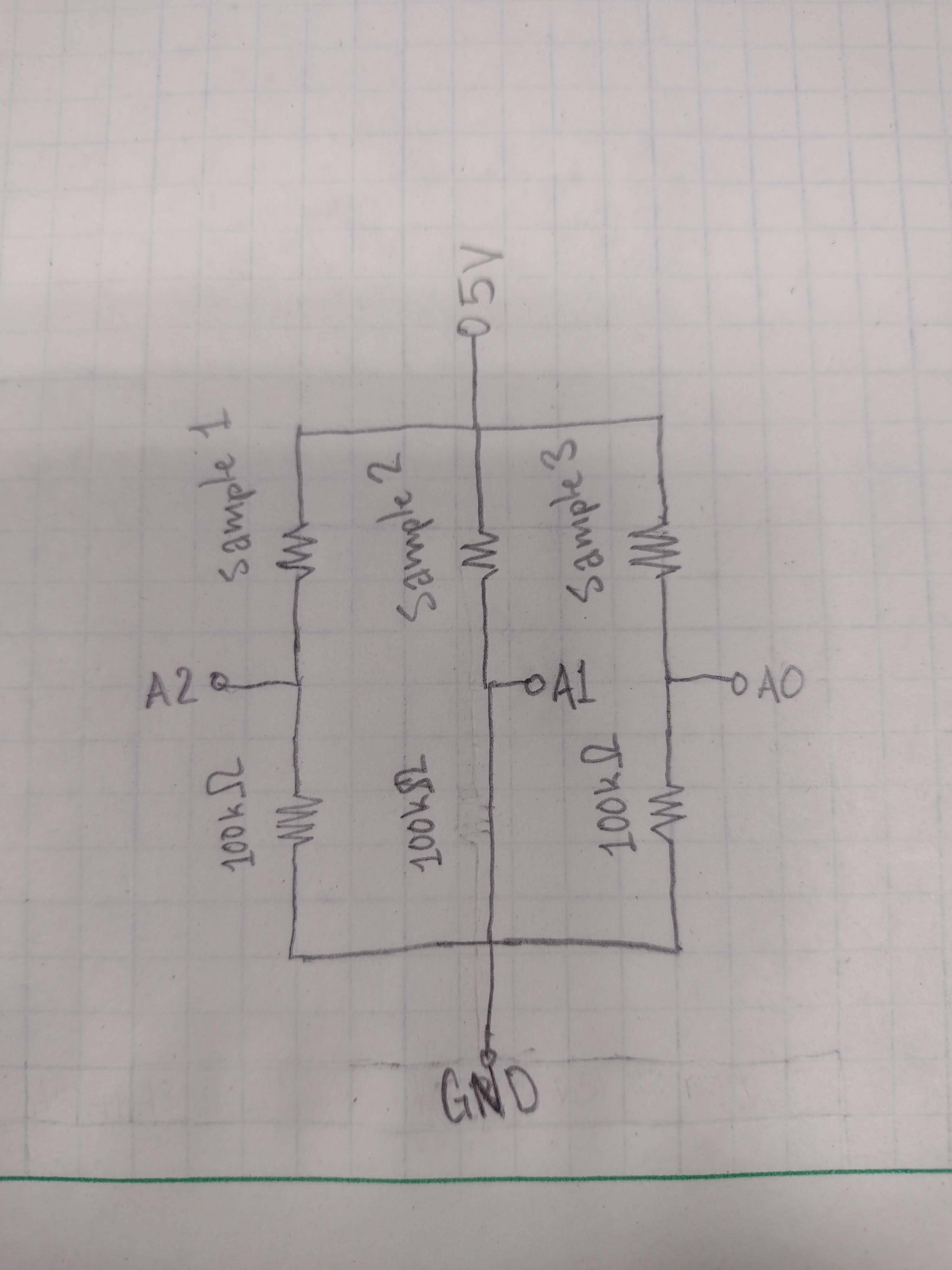
Above is an image of the theory of how this is supposed to work with a single analog pin (my resistors are 100kOhms, not 117kOhms). I am attempting to measure the resistance of a membrane, with two electrodes on each side, one of which is the power supply and the other 3 are sensors. I have left the 5V unconnected as I am trying to do preliminary testing to ensure that the wiring works before connecting the entire system to measure the membrane resistance. The 5V will eventually be connected through an imaginary 4th resistor, i.e., the membrane. The image below should illustrate my goal, I am just at the "testing each electrode individually" stage before proceeding to that point.
Imagine E1 as the 5V, with E2, E3, and E4 as A0, A1, and A2, respectively. My goal is to measure some R_m, with R_1 and R_3 the resistor in line with A0, R_1, R_3, and R_4 as the resistor in line with A1, and R_1, R_3, and R_2 as the resistor in line with A2. Hopefully that makes sense as to why it's not connected and why I need to isolate the "phantom" readings when the 5V isn't connected to anything.
Can you please post a copy of your circuit, a picture of a hand drawn circuit in jpg, png?
Hand drawn and photographed is perfectly acceptable.
Please include ALL hardware, power supplies, component names and pin labels.
Indicating where you are disconnecting the 5V.
Are you aware that without the 5V connected, you will have no current flowing through your resistor network, so no voltdrop to measure across the resistors.
This might help.
What do you expect to get with no 5V supply connected to your network?
I am splitting the 5V power supply, then measuring the voltage drop at the analog pins, then relating that to the voltage drop to 0 at ground across a known resistor for each parallel.
When I have no power going to the system (i.e., the 5V not connected), I expect to see "inf;inf;inf" as the output.
The A0, A1, A2 readings. When R2, R3, and R4 are calculated then printed in the void loop with nothing connected, they should output "inf," basically saying that there is a divide by zero error because there is no voltage drop.
You are loading your divider circuit with the input impedance of the A/D. This is swamping your input circuit. Put a 100 nF on that point and give it time to charge. The reason is when the A/D samples it draws a finite amount of current from its input.
These are due to the PCB construction material, soldering residues, external wiring, integrated die problems, contaminants, non ideal components (ex. capacitors) etc.
My apologies for not understanding, but could you explain this to me? I don't know what A/D is, and I'm unsure of what "swamping" a circuit means.
To clarify the one thing I think I understand, do you mean put a 100nF capacitor between the 5V source and the split of the circuit into parallels and add a longer delay to the void loop startup?
The cap would be between A0 and ground. The A/D (Analog to Digital converter), is part of the chip that converts the analog input to a digital value does not have an infinite (does not have any) resistance therefore it does have resistance(impedance). Therefore that resistance is applied parallel to your input circuit. You could also place an Op-Amp in the input circuit set up as unity gain to eliminate the A0 loading. Schematic shown below. You will need to be careful of your choice as not all op-amps will swing rail to rail.
What @gilshultz suggests is certainly worth considering. However, I'd also suggest working with a more stable reference voltage instead if the 5V supply voltage. You could e.g. use the internal 1.1V reference on the Arduino, or a dedicated and stable external reference which you apply to the Arduino's Aref.
Using the 5V supply voltage as a reference works well enough if "close enough for government work" is OK. However, if you want to squeeze the last bit of resolution from the A/D (analog/digital) converter, it's a good idea to work with a stable analog reference - and also to spend attention on circuit layout, and in particular grounding. Currents through your ground wires can create small potential differences between the GND of your DUT (device under test) and the Arduino (i.e. the ADC). These add up/subtract from your ADC measurements.
I made an incorrect assumption when trying to validate each individual analog pin reading. I assumed the wild fluctuations would persist when the additional resistors were installed, making every reading fluctuate wildly, but I installed 3 resistors and it worked fine. I guess it just means that while the actual sample "resistors" are not being measured, the device will give wild readings, but will stabilize when it is inserted into the sample.