Hello,
I'm new to the whole Arduino world and I like some help identifying a couple of controllers on the board.
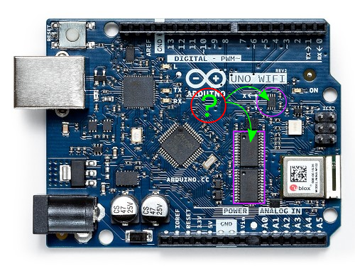
I have looked at the PCB diagrams but all I can see is U502, U504 (the two in the rectangle), and U601 (the one in the circle).
I think the U601(circle) is the bidirectional voltage level converter but I'm not sure.
I'd really appreciate any advice anyone could give me.
Thank you very much for your advice @missdrew, it is greatly appreciated!
I did look through the schematic but it was quite confusing (being the first time I'd seen one).
I was able to find the 74LVX4245 (rectangle), which is an 8 Bit Dual Supply Translating Transceiver and the TS0102 (circle) which I think the schematic says is a 2 Bits Level Shifter.
The schematic has a pair of 16 Bits Level Shifter on page 9 so I suppose that would be the two 74LVX4245s?
What I'm now not sure about is what they are doing differently if they are both voltage level translators?
Anyway, you made me revisit the schematic, which was great! I'd kind of given up on trying to understand it.
Once again, thank you for your advice.
I used Eagle v7.7.0 to open the files. There are a few complaints from the program as that version is quite old, but I think it is the last version that had the free 2 layer option.
The newer files are all based around XML so in theory you could also open them with a text editor and see their innards, but I don't know if you would get the complete story that way.
Hello @markd833,
Thank you very much for your advice! I was able get Eagle 9.6.2 up and running and that has given me a wealth of information. I also opened the file in my text editor, as you suggested, and that too worked a treat.
Once again, thank you so much for all of your help. Sorry for the late reply.