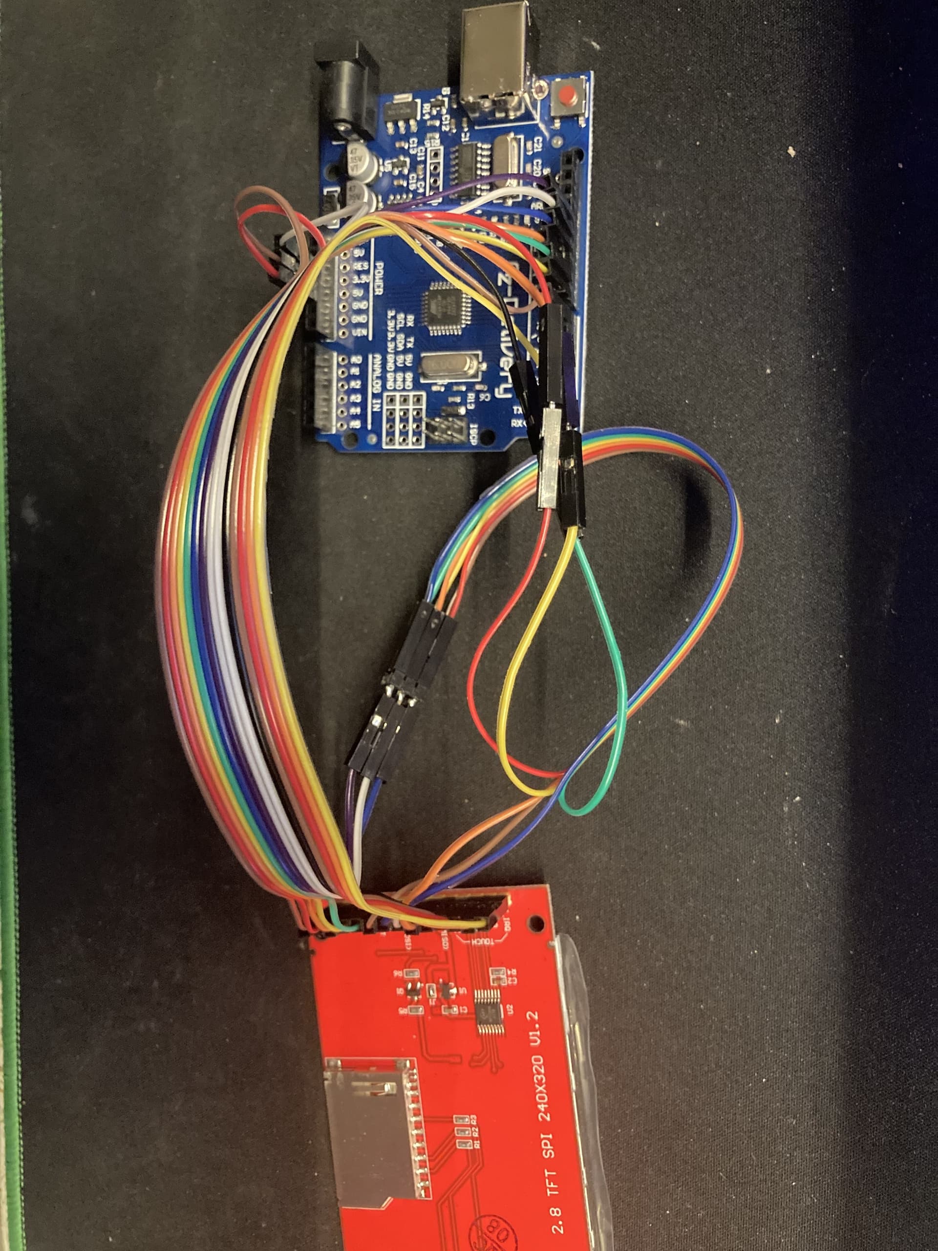
I have an "az-atmega328-board" and a "2,8 Zoll LCD TFT Touch Display - Kompatibel mit Arduino und Raspberry Pi - 320x240px Auflösung, ILI9341 Treiber, SPI Schnitts".
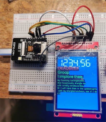
Why is the screen white but not displaying anything i have the pins like this:
VCC is in 5V
GND is in GND
CS is in Digital Pin 10
RESET is in Digital Pin 8
DC is in Digital Pin 9
SDI/MOSI is in Digital Pin 11
SCK is in Digital Pin 13
LED is in 3.3V
SDOK/MISO is in Digital Pin 12
The touch pins are:
T_CLK is in Digital Pin 13
T_CS is in Digital Pin 7
T_DIN is in Digital Pin 11
T_DO is in Digital Pin 12
T_IRQ is in Digital Pin 2
Any help?
  This is our touchscreen painting example for the Adafruit ILI9341 Breakout
  ----> http://www.adafruit.com/products/1770

  Check out the links above for our tutorials and wiring diagrams
  These displays use SPI to communicate, 4 or 5 pins are required to
  interface (RST is optional)
  Adafruit invests time and resources providing this open source code,
  please support Adafruit and open-source hardware by purchasing
  products from Adafruit!

  Written by Limor Fried/Ladyada for Adafruit Industries.
  MIT license, all text above must be included in any redistribution
 ****************************************************/

/** NOT FOR USE WITH THE TOUCH SHIELD, ONLY FOR THE BREAKOUT! **/

#include <Adafruit_GFX.h>    // Core graphics library
#include <SPI.h>
#include <Adafruit_ILI9341.h>
#include "TouchScreen.h"

// These are the four touchscreen analog pins
#define YP A2  // must be an analog pin, use "An" notation!
#define XM A3  // must be an analog pin, use "An" notation!
#define YM 8   // can be any digital pin
#define XP 9   // can be any digital pin

// This is calibration data for the raw touch data to the screen coordinates
#define TS_MINX 150
#define TS_MINY 120
#define TS_MAXX 920
#define TS_MAXY 940

#define MINPRESSURE 10
#define MAXPRESSURE 1000

// The display uses hardware SPI, plus #9 & #10
#define TFT_CS 10
#define TFT_DC 9
Adafruit_ILI9341 tft = Adafruit_ILI9341(TFT_CS, TFT_DC);

// For better pressure precision, we need to know the resistance
// between X+ and X- Use any multimeter to read it
// For the one we're using, its 300 ohms across the X plate
TouchScreen ts = TouchScreen(XP, YP, XM, YM, 300);

// Size of the color selection boxes and the paintbrush size
#define BOXSIZE 40
#define PENRADIUS 3
int oldcolor, currentcolor;

void setup(void) {
 // while (!Serial);     // used for leonardo debugging

  Serial.begin(9600);
  Serial.println(F("Touch Paint!"));

  tft.begin();
  tft.fillScreen(ILI9341_BLACK);

  // make the color selection boxes
  tft.fillRect(0, 0, BOXSIZE, BOXSIZE, ILI9341_RED);
  tft.fillRect(BOXSIZE, 0, BOXSIZE, BOXSIZE, ILI9341_YELLOW);
  tft.fillRect(BOXSIZE*2, 0, BOXSIZE, BOXSIZE, ILI9341_GREEN);
  tft.fillRect(BOXSIZE*3, 0, BOXSIZE, BOXSIZE, ILI9341_CYAN);
  tft.fillRect(BOXSIZE*4, 0, BOXSIZE, BOXSIZE, ILI9341_BLUE);
  tft.fillRect(BOXSIZE*5, 0, BOXSIZE, BOXSIZE, ILI9341_MAGENTA);

  // select the current color 'red'
  tft.drawRect(0, 0, BOXSIZE, BOXSIZE, ILI9341_WHITE);
  currentcolor = ILI9341_RED;
}


void loop()
{
  // Retrieve a point
  TSPoint p = ts.getPoint();

 /*
  Serial.print("X = "); Serial.print(p.x);
  Serial.print("\tY = "); Serial.print(p.y);
  Serial.print("\tPressure = "); Serial.println(p.z);
 */

  // we have some minimum pressure we consider 'valid'
  // pressure of 0 means no pressing!
  if (p.z < MINPRESSURE || p.z > MAXPRESSURE) {
     return;
  }

  // Scale from ~0->1000 to tft.width using the calibration #'s
  p.x = map(p.x, TS_MINX, TS_MAXX, 0, tft.width());
  p.y = map(p.y, TS_MINY, TS_MAXY, 0, tft.height());

  /*
  Serial.print("("); Serial.print(p.x);
  Serial.print(", "); Serial.print(p.y);
  Serial.println(")");
  */


  if (p.y < BOXSIZE) {
     oldcolor = currentcolor;

     if (p.x < BOXSIZE) {
       currentcolor = ILI9341_RED;
       tft.drawRect(0, 0, BOXSIZE, BOXSIZE, ILI9341_WHITE);
     } else if (p.x < BOXSIZE*2) {
       currentcolor = ILI9341_YELLOW;
       tft.drawRect(BOXSIZE, 0, BOXSIZE, BOXSIZE, ILI9341_WHITE);
     } else if (p.x < BOXSIZE*3) {
       currentcolor = ILI9341_GREEN;
       tft.drawRect(BOXSIZE*2, 0, BOXSIZE, BOXSIZE, ILI9341_WHITE);
     } else if (p.x < BOXSIZE*4) {
       currentcolor = ILI9341_CYAN;
       tft.drawRect(BOXSIZE*3, 0, BOXSIZE, BOXSIZE, ILI9341_WHITE);
     } else if (p.x < BOXSIZE*5) {
       currentcolor = ILI9341_BLUE;
       tft.drawRect(BOXSIZE*4, 0, BOXSIZE, BOXSIZE, ILI9341_WHITE);
     } else if (p.x < BOXSIZE*6) {
       currentcolor = ILI9341_MAGENTA;
       tft.drawRect(BOXSIZE*5, 0, BOXSIZE, BOXSIZE, ILI9341_WHITE);
     }

     if (oldcolor != currentcolor) {
        if (oldcolor == ILI9341_RED)
          tft.fillRect(0, 0, BOXSIZE, BOXSIZE, ILI9341_RED);
        if (oldcolor == ILI9341_YELLOW)
          tft.fillRect(BOXSIZE, 0, BOXSIZE, BOXSIZE, ILI9341_YELLOW);
        if (oldcolor == ILI9341_GREEN)
          tft.fillRect(BOXSIZE*2, 0, BOXSIZE, BOXSIZE, ILI9341_GREEN);
        if (oldcolor == ILI9341_CYAN)
          tft.fillRect(BOXSIZE*3, 0, BOXSIZE, BOXSIZE, ILI9341_CYAN);
        if (oldcolor == ILI9341_BLUE)
          tft.fillRect(BOXSIZE*4, 0, BOXSIZE, BOXSIZE, ILI9341_BLUE);
        if (oldcolor == ILI9341_MAGENTA)
          tft.fillRect(BOXSIZE*5, 0, BOXSIZE, BOXSIZE, ILI9341_MAGENTA);
     }
  }
  if (((p.y-PENRADIUS) > BOXSIZE) && ((p.y+PENRADIUS) < tft.height())) {
    tft.fillCircle(p.x, p.y, PENRADIUS, currentcolor);
  }
}```