Hi,
I am always looking for a sketch that works with the ESP32 DEVKIT V1 and the ILI9341 display.
I found in the Adafruit TouchScreen examples this sketch:
// Touch screen library with X Y and Z (pressure) readings as well
  // as oversampling to avoid 'bouncing'
  // This demo code returns raw readings, public domain

  #include <stdint.h>
  #include "TouchScreen.h"

  #define YP A2  // must be an analog pin, use "An" notation!
  #define XM A3  // must be an analog pin, use "An" notation!
  #define YM 8   // can be a digital pin
  #define XP 9   // can be a digital pin

  // For better pressure precision, we need to know the resistance
  // between X+ and X- Use any multimeter to read it
  // For the one we're using, its 300 ohms across the X plate
  TouchScreen ts = TouchScreen(XP, YP, XM, YM, 300);

  void setup(void) {
    Serial.begin(9600);
  }

  void loop(void) {
    // a point object holds x y and z coordinates
    TSPoint p = ts.getPoint();

    // we have some minimum pressure we consider 'valid'
    // pressure of 0 means no pressing!
    if (p.z > ts.pressureThreshhold) {
       Serial.print("X = "); Serial.print(p.x);
       Serial.print("\tY = "); Serial.print(p.y);
       Serial.print("\tPressure = "); Serial.println(p.z);
    }

    delay(100);
  }
But a problem immediately arises for me.
To which pins of the ILI9341 display should I associate the four pins of the #defines.
I couldn't find any information.
Any advice is welcome
I know what are the analog pins and digital pins of ESP32.
But my problem is to associate #define YP A2, #define XM A3, #define YM 8, #define XP 9 with which of the 14pins on the ILI9341.
Which of the 9 pins that are needed for the display or the 5 pins that are needed for the touch.
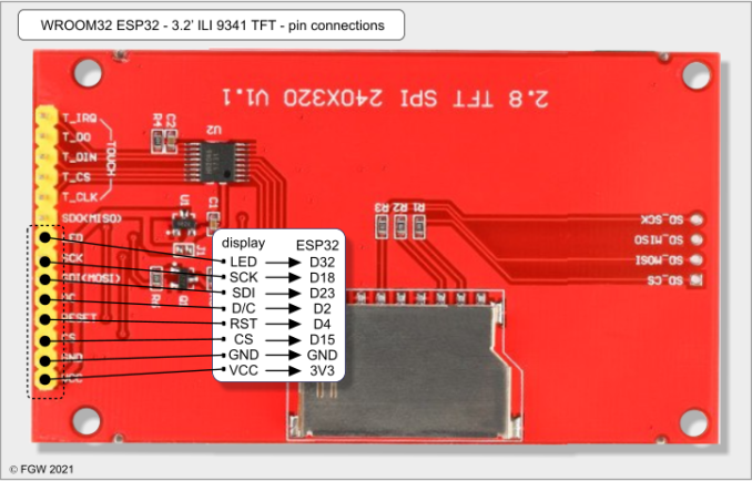
// toutch screen connections
// connect T_CS to GPIO 5
// T_CLK to GPIO 18 CLK
// T_DO to GPIO 19 MISO
// T_DIN to GPIO 23 MOSI
// This sketch is to test the touch controller, nothing is displayed
// on the TFT. The TFT_eSPI library must be configured to suit your
// pins used. Make sure both the touch chip select and the TFT chip
// select are correctly defined to avoid SPI bus contention.
// Make sure you have defined a pin for the touch controller chip
// select line in the user setup file or you will see "no member"
// compile errors for the touch functions!
// It is a support and diagnostic sketch for the TFT_eSPI library:
// https://github.com/Bodmer/TFT_eSPI
// The "raw" (unprocessed) touch sensor outputs are sent to the
// serial port. Touching the screen should show changes to the x, y
// and z values. x and y are raw ADC readings, not pixel coordinates.
#include <SPI.h>
#include <TFT_eSPI.h>
TFT_eSPI tft = TFT_eSPI();
//====================================================================
void setup(void) {
Serial.begin(115200);
Serial.println("\n\nStarting...");
tft.init();
}
//====================================================================
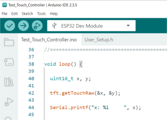
void loop() {
uint16_t x, y;
tft.getTouchRaw(&x, &y);
Serial.printf("x: %i ", x);
Serial.printf("y: %i ", y);
Serial.printf("z: %i \n", tft.getTouchRawZ());
delay(500);
}
//====================================================================
User_Setup.h file (place in same directory as the above Test_Touch_Controller.ino file
// TFT_eSPI setup.h file for Arduino Due Module
// RP2040 Waveshare General 2inch LCD Display Module IPS Screen 240×320 ST7789

#define USER_SETUP_INFO "User_Setup"

#define ILI9341_DRIVER

// For ST7735, ST7789 and ILI9341 ONLY, define the colour order IF the blue and red are swapped on your display
// Try ONE option at a time to find the correct colour order for your display
//  #define TFT_RGB_ORDER TFT_RGB  // Colour order Red-Green-Blue
//  #define TFT_RGB_ORDER TFT_BGR  // Colour order Blue-Green-Red

// For ST7789, ST7735, ILI9163 and GC9A01 ONLY, define the pixel width and height in portrait orientation
#define TFT_WIDTH  240 // ST7789 240 x 240 and 240 x 320
#define TFT_HEIGHT 320 // ST7789 240 x 320

// If colours are inverted (white shows as black) then uncomment one of the next
// 2 lines try both options, one of the options should correct the inversion.

// #define TFT_INVERSION_ON
// #define TFT_INVERSION_OFF

#define TFT_CS   15
#define TFT_MOSI MOSI
#define TFT_SCLK SCK
#define TFT_MISO MISO

#define TFT_DC   2
#define TFT_RST  4

#define TOUCH_CS 5    // toutch screen CS pin

#define LOAD_GLCD
#define LOAD_FONT2
#define LOAD_FONT4
#define LOAD_FONT6
#define LOAD_FONT7
#define LOAD_FONT8
#define LOAD_GFXFF

#define SMOOTH_FONT

#define SPI_FREQUENCY   10000000

#define SPI_TOUCH_FREQUENCY  2500000
serial monitor output as the pen is moved around the screen
I copied the sketch and the User_Setup and put them in the same directory.
When I compile it it gives me this error:
Arduino:1.8.19 (Mac OS X), Scheda:"ESP32 Dev Module, Disabled, Disabled, Default 4MB with spiffs (1.2MB APP/1.5MB SPIFFS), 240MHz (WiFi/BT), QIO, 80MHz, 4MB (32Mb), 921600, Core 1, Core 1, None, Disabled"

/Users/ezio/Desktop/Test_Touch_Controllr/Test_Touch_Controllr.ino: In function 'void loop()':
Test_Touch_Controllr:43:7: error: 'class TFT_eSPI' has no member named 'getTouchRaw'
   tft.getTouchRaw(&x, &y);
       ^~~~~~~~~~~
Test_Touch_Controllr:49:33: error: 'class TFT_eSPI' has no member named 'getTouchRawZ'
   Serial.printf("z: %i \n", tft.getTouchRawZ());
                                 ^~~~~~~~~~~~
exit status 1
'class TFT_eSPI' has no member named 'getTouchRaw'
I rechecked the connections a couple of times and they are correct.
Especially T_CLK, T_DO and T_DIN.
I am stranded
thinking again - did you copy the User_Setup.h file in to the same directory (Windows calls them Folders) as the test program .ino file?
the IDE should show tabs for the .ino and User_Setup.h files
I copied and verified the User_Setup.h.
It is in the same folder as the .ino file.
The T_Cs is connected to the GPIO5.
The version of ESP32 that I use is 2.0.17.
If I update it to version 3.2.0 it gives me this error:
Arduino:1.8.19 (Mac OS X), Scheda:"ESP32 Dev Module, Disabled, Disabled, Default 4MB with spiffs (1.2MB APP/1.5MB SPIFFS), 240MHz (WiFi/BT), QIO, 80MHz, 4MB (32Mb), 921600, Core 1, Core 1, None, Disabled, Disabled"
[8206] Error loading Python lib '/var/folders/sf/6l3wtqc949v0lvxt3030y21m0000gn/T/_MEIXQ3MAj/libpython3.8.dylib': dlopen: dlopen(/var/folders/sf/6l3wtqc949v0lvxt3030y21m0000gn/T/_MEIXQ3MAj/libpython3.8.dylib, 10): Symbol not found: _preadv
  Referenced from: /var/folders/sf/6l3wtqc949v0lvxt3030y21m0000gn/T/_MEIXQ3MAj/libpython3.8.dylib (which was built for Mac OS X 12.7)
  Expected in: /usr/lib/libSystem.B.dylib

exit status 255
/Applications/Arduino.app/Contents/Java/arduino-builder ha restituito 255
I installed ESP32 version 3.0.0 and the sketch works.
I see on the Serial Monitor the numbers changing if I press on the display.
With versions of ESP32 higher than 3.0.0 it gives me the previous error.