Help on an ESP32 C3 Super Mini Project (Clock)

Hello friends,
the info in this forum already was of great help to me to get the ESP32 flashed properly.
So, this is the project I've been trying to build:

So far, I managed to test whether the board is logging into my network. Which was positive. Does that mean, the ESP32 was flashed properly?

Anyway, my problem: That's all of it. The OLED screen doesn't power up and that LED isn't flashing.

What I just realized is that in that video tutorial, I can see the blue onboard LED is flashing which doesn't happen on mine. (I did test it though with a little flashing code)
And this is my stuff on the breadboard:

Please post a link to the datasheet. There are plenty of different OLEDs.

What is the the circuit in the middle, in the diagram picture, supposed to do?

Thanks, I got it from Aliexpress (I2C SSD1306), and this should be its datasheet:

What is the the circuit in the middle, in the diagram picture, supposed to do?

That is the sht31, a temperature and humidity sensor. Forgot to add to say that, sorry. been troubleshooting a while.

It has a datasheet I suppose


While trouble shooting the display, please disconnect it. There’s a question about external pull up needed or not.

Sorry, sure (sht31)

Without any sensors and display, it did boot up and connected to my wifi.

That’s positive.

Connect only one new item at the time and make the code handle it.

At some point the code will be requested. How to is described in the link: How to get the best out of this forum - Development Tools / IDE 1.x - Arduino Forum “Code problems
”

I have several comments on that project.
The author seems from Vietnam, judging from the comments, where daylightsavings is not observed. The code uses the now obsolete NTPCLient library. This will be a pain in a country where DST is observed, meaning you must re-upload new corrected time code twice a year.
The current ESP core allows for a much easier NTP update with location string that automagically corrects for DST.

The code does leave the WiFi radio on all the time, draining the battery much faster than needed. WiFi only needs to be on during the short NTP updates.

If a board with battery management and protected cell was used, then the charger module
could have been omited. XIAO ESP32C3 boards have such built-in battery management.

The Aliexpress ESP32-C3 could be problematic.
Leo..

#define LED_PIN 0
The LED is connected to GPIO8 on a supermini, not D0.
The author has chosen to use D8,9 for I2C instead of the default D4,5.
Seems like a clash with I2C.
Leo..

I wasn’t sure up to now whether I can post the code directly here as it’s not my own. So here is the programm code:


#include <WiFi.h>
#include <Wire.h>
#include <Adafruit_GFX.h>
#include <Adafruit_SSD1306.h>
#include <Adafruit_SHT31.h>
#include <NTPClient.h>
#include <WiFiUdp.h>

// ===== WiFi info =====
const char* ssid     = "Your_Wifi";
const char* password = "Pass";

// ===== OLED setup =====
#define SCREEN_WIDTH 128
#define SCREEN_HEIGHT 32
Adafruit_SSD1306 display(SCREEN_WIDTH, SCREEN_HEIGHT, &Wire, -1);

// ===== SHT31 setup =====
Adafruit_SHT31 sht31 = Adafruit_SHT31();

// ===== NTP setup =====
WiFiUDP ntpUDP;
NTPClient timeClient(ntpUDP, "pool.ntp.org", 7 * 3600, 60000); // GMT+7

// ===== Pins  =====
#define I2C_SDA 8
#define I2C_SCL 9
#define LED_PIN 0

// LED
unsigned long lastBlink = 0;

void setup() {
  Serial.begin(115200);
  Wire.begin(I2C_SDA, I2C_SCL);

  // WiFi
  WiFi.begin(ssid, password);
  while (WiFi.status() != WL_CONNECTED) {
    delay(500);
    Serial.print(".");
  }
  Serial.println("\nWiFi connected!");

  // OLED init
  if (!display.begin(SSD1306_SWITCHCAPVCC, 0x3C)) {
    Serial.println(F("SSD1306 allocation failed"));
    for (;;);
  }
  display.clearDisplay();
  display.setRotation(1);
  display.display();

  // SHT31 init
  if (!sht31.begin(0x44)) {
    Serial.println("Couldn't find SHT31");
    while (1) delay(1);
  }

  // NTP init
  timeClient.begin();

  // LED init
  pinMode(LED_PIN, OUTPUT);
  digitalWrite(LED_PIN, LOW);
}

void loop() {
  timeClient.update();

  int hours = timeClient.getHours();
  int minutes = timeClient.getMinutes();
  int seconds = timeClient.getSeconds();

  // AM/PM
  bool isPM = false;
  if (hours >= 12) {
    isPM = true;
    if (hours > 12) hours -= 12;
  }
  if (hours == 0) hours = 12;

  // Ă„ÂĂĄÂ»Âc cĂĄÂșÂŁm biĂĄÂșÂżn
  float tempC = sht31.readTemperature();
  float hum   = sht31.readHumidity();

  // Format chu廗i
  char hStr[3], mStr[3], sStr[3];
  sprintf(hStr, "%02d", hours);
  sprintf(mStr, "%02d", minutes);
  sprintf(sStr, "%02d", seconds);

  // ===== OLED =====
  display.clearDisplay();
  display.setTextColor(SSD1306_WHITE);

  // Header
  display.setTextSize(0.5);
  display.setCursor(2, 0);
  display.println("/////");
  display.setCursor(60, 10);
  display.println(isPM ? "PM" : "AM");
  display.drawLine(0, 10, 128, 10, SSD1306_WHITE);

  // hh
  display.setTextSize(2);
  display.setCursor(5, 30);
  display.println(hStr);

  // mm
  display.setTextSize(2);
  display.setCursor(5, 52);
  display.println(mStr);

  // ss
  display.setTextSize(2);
  display.setCursor(5, 72);
  display.println(sStr);

  // --------
  display.drawLine(0, 95, 128, 95, SSD1306_WHITE);

  // (°C) & Đ廙 ĂĄÂș©m
  display.setTextSize(1);
  display.setCursor(5, 105);
  display.print((int)tempC);
  display.print((char)247); // kĂƒÂœ hi廇u °
  display.print("C");
  display.setCursor(5, 120);
  display.print((int)hum);
  display.print("%");

  display.display();

  // ===== LED =====
  unsigned long now = millis();
  if (now - lastBlink >= 5000) {  // m廗i 5 giùy
    digitalWrite(LED_PIN, HIGH);
    delay(20);                    // sång 20 ms
    digitalWrite(LED_PIN, LOW);
    lastBlink = now;
  }

  delay(200); // giĂĄÂșÂŁm tĂĄÂșÂŁi CPU
}

Thanks for the Information :slight_smile:
I‘m still starting out so it‘s really interesting to me.
I was hoping that it wasn‘t any incompatibilty or so.
Do you have an idea/link how to test the OLED in a minimal configuration?
I‘ll keep trying it out.

I managed to generate an output with this thread :slight_smile:

Going on, next steps ...

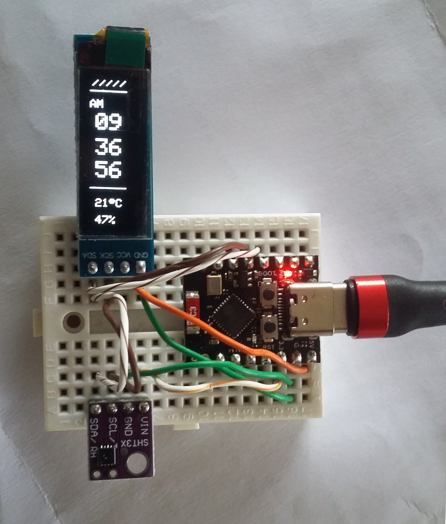
Ok, so after a few hours, I'm not any further :frowning:
So using this code for testscreen, I even use the same pins (8 and 9) as in the code for the clock project above. I get the test proper testscreens.

/**************************************************************************
 This is an example for our Monochrome OLEDs based on SSD1306 drivers

 Pick one up today in the adafruit shop!
 ------> http://www.adafruit.com/category/63_98

 This example is for a 128x64 pixel display using I2C to communicate
 3 pins are required to interface (two I2C and one reset).

 Adafruit invests time and resources providing this open
 source code, please support Adafruit and open-source
 hardware by purchasing products from Adafruit!

 Written by Limor Fried/Ladyada for Adafruit Industries,
 with contributions from the open source community.
 BSD license, check license.txt for more information
 All text above, and the splash screen below must be
 included in any redistribution.
 **************************************************************************/

#include <SPI.h>
#include <Wire.h>
#include <Adafruit_GFX.h>
#include <Adafruit_SSD1306.h>

#define SCREEN_WIDTH 128 // OLED display width, in pixels
#define SCREEN_HEIGHT 32 // OLED display height, in pixels

// Declaration for an SSD1306 display connected to I2C (SDA, SCL pins)
// The pins for I2C are defined by the Wire-library. 
// On an arduino UNO:       A4(SDA), A5(SCL)
// On an arduino MEGA 2560: 20(SDA), 21(SCL)
// On an arduino LEONARDO:   2(SDA),  3(SCL), ...
#define OLED_RESET     -1 // Reset pin # (or -1 if sharing Arduino reset pin)
#define SCREEN_ADDRESS 0x3C //0x3D ///< See datasheet for Address; 0x3D for 128x64, 0x3C for 128x32
Adafruit_SSD1306 display(SCREEN_WIDTH, SCREEN_HEIGHT, &Wire, OLED_RESET);

#define NUMFLAKES     10 // Number of snowflakes in the animation example

#define LOGO_HEIGHT   16
#define LOGO_WIDTH    16
static const unsigned char PROGMEM logo_bmp[] =
{ 0b00000000, 0b11000000,
  0b00000001, 0b11000000,
  0b00000001, 0b11000000,
  0b00000011, 0b11100000,
  0b11110011, 0b11100000,
  0b11111110, 0b11111000,
  0b01111110, 0b11111111,
  0b00110011, 0b10011111,
  0b00011111, 0b11111100,
  0b00001101, 0b01110000,
  0b00011011, 0b10100000,
  0b00111111, 0b11100000,
  0b00111111, 0b11110000,
  0b01111100, 0b11110000,
  0b01110000, 0b01110000,
  0b00000000, 0b00110000 };

void setup() {
  Serial.begin(115200);
  Wire.begin(8,9);      
  // SSD1306_SWITCHCAPVCC = generate display voltage from 3.3V internally
  if(!display.begin(SSD1306_SWITCHCAPVCC, SCREEN_ADDRESS)) {
    Serial.println(F("SSD1306 allocation failed"));
    for(;;); // Don't proceed, loop forever
  }
    Serial.println(F("SSD1306 allocation OK"));

  // Show initial display buffer contents on the screen --
  // the library initializes this with an Adafruit splash screen.
  display.display();
  delay(2000); // Pause for 2 seconds

  // Clear the buffer
  display.clearDisplay();

  // Draw a single pixel in white
  display.drawPixel(10, 10, SSD1306_WHITE);

  // Show the display buffer on the screen. You MUST call display() after
  // drawing commands to make them visible on screen!
  display.display();
  delay(2000);
  // display.display() is NOT necessary after every single drawing command,
  // unless that's what you want...rather, you can batch up a bunch of
  // drawing operations and then update the screen all at once by calling
  // display.display(). These examples demonstrate both approaches...

  testdrawline();      // Draw many lines

  testdrawrect();      // Draw rectangles (outlines)

  testfillrect();      // Draw rectangles (filled)

  testdrawcircle();    // Draw circles (outlines)

  testfillcircle();    // Draw circles (filled)

  testdrawroundrect(); // Draw rounded rectangles (outlines)

  testfillroundrect(); // Draw rounded rectangles (filled)

  testdrawtriangle();  // Draw triangles (outlines)

  testfilltriangle();  // Draw triangles (filled)

  testdrawchar();      // Draw characters of the default font

  testdrawstyles();    // Draw 'stylized' characters

  testscrolltext();    // Draw scrolling text

  testdrawbitmap();    // Draw a small bitmap image

  // Invert and restore display, pausing in-between
  display.invertDisplay(true);
  delay(1000);
  display.invertDisplay(false);
  delay(1000);

  testanimate(logo_bmp, LOGO_WIDTH, LOGO_HEIGHT); // Animate bitmaps
}

void loop() {
}

void testdrawline() {
  int16_t i;

  display.clearDisplay(); // Clear display buffer

  for(i=0; i<display.width(); i+=4) {
    display.drawLine(0, 0, i, display.height()-1, SSD1306_WHITE);
    display.display(); // Update screen with each newly-drawn line
    delay(1);
  }
  for(i=0; i<display.height(); i+=4) {
    display.drawLine(0, 0, display.width()-1, i, SSD1306_WHITE);
    display.display();
    delay(1);
  }
  delay(250);

  display.clearDisplay();

  for(i=0; i<display.width(); i+=4) {
    display.drawLine(0, display.height()-1, i, 0, SSD1306_WHITE);
    display.display();
    delay(1);
  }
  for(i=display.height()-1; i>=0; i-=4) {
    display.drawLine(0, display.height()-1, display.width()-1, i, SSD1306_WHITE);
    display.display();
    delay(1);
  }
  delay(250);

  display.clearDisplay();

  for(i=display.width()-1; i>=0; i-=4) {
    display.drawLine(display.width()-1, display.height()-1, i, 0, SSD1306_WHITE);
    display.display();
    delay(1);
  }
  for(i=display.height()-1; i>=0; i-=4) {
    display.drawLine(display.width()-1, display.height()-1, 0, i, SSD1306_WHITE);
    display.display();
    delay(1);
  }
  delay(250);

  display.clearDisplay();

  for(i=0; i<display.height(); i+=4) {
    display.drawLine(display.width()-1, 0, 0, i, SSD1306_WHITE);
    display.display();
    delay(1);
  }
  for(i=0; i<display.width(); i+=4) {
    display.drawLine(display.width()-1, 0, i, display.height()-1, SSD1306_WHITE);
    display.display();
    delay(1);
  }

  delay(2000); // Pause for 2 seconds
}

void testdrawrect(void) {
  display.clearDisplay();

  for(int16_t i=0; i<display.height()/2; i+=2) {
    display.drawRect(i, i, display.width()-2*i, display.height()-2*i, SSD1306_WHITE);
    display.display(); // Update screen with each newly-drawn rectangle
    delay(1);
  }

  delay(2000);
}

void testfillrect(void) {
  display.clearDisplay();

  for(int16_t i=0; i<display.height()/2; i+=3) {
    // The INVERSE color is used so rectangles alternate white/black
    display.fillRect(i, i, display.width()-i*2, display.height()-i*2, SSD1306_INVERSE);
    display.display(); // Update screen with each newly-drawn rectangle
    delay(1);
  }

  delay(2000);
}

void testdrawcircle(void) {
  display.clearDisplay();

  for(int16_t i=0; i<max(display.width(),display.height())/2; i+=2) {
    display.drawCircle(display.width()/2, display.height()/2, i, SSD1306_WHITE);
    display.display();
    delay(1);
  }

  delay(2000);
}

void testfillcircle(void) {
  display.clearDisplay();

  for(int16_t i=max(display.width(),display.height())/2; i>0; i-=3) {
    // The INVERSE color is used so circles alternate white/black
    display.fillCircle(display.width() / 2, display.height() / 2, i, SSD1306_INVERSE);
    display.display(); // Update screen with each newly-drawn circle
    delay(1);
  }

  delay(2000);
}

void testdrawroundrect(void) {
  display.clearDisplay();

  for(int16_t i=0; i<display.height()/2-2; i+=2) {
    display.drawRoundRect(i, i, display.width()-2*i, display.height()-2*i,
      display.height()/4, SSD1306_WHITE);
    display.display();
    delay(1);
  }

  delay(2000);
}

void testfillroundrect(void) {
  display.clearDisplay();

  for(int16_t i=0; i<display.height()/2-2; i+=2) {
    // The INVERSE color is used so round-rects alternate white/black
    display.fillRoundRect(i, i, display.width()-2*i, display.height()-2*i,
      display.height()/4, SSD1306_INVERSE);
    display.display();
    delay(1);
  }

  delay(2000);
}

void testdrawtriangle(void) {
  display.clearDisplay();

  for(int16_t i=0; i<max(display.width(),display.height())/2; i+=5) {
    display.drawTriangle(
      display.width()/2  , display.height()/2-i,
      display.width()/2-i, display.height()/2+i,
      display.width()/2+i, display.height()/2+i, SSD1306_WHITE);
    display.display();
    delay(1);
  }

  delay(2000);
}

void testfilltriangle(void) {
  display.clearDisplay();

  for(int16_t i=max(display.width(),display.height())/2; i>0; i-=5) {
    // The INVERSE color is used so triangles alternate white/black
    display.fillTriangle(
      display.width()/2  , display.height()/2-i,
      display.width()/2-i, display.height()/2+i,
      display.width()/2+i, display.height()/2+i, SSD1306_INVERSE);
    display.display();
    delay(1);
  }

  delay(2000);
}

void testdrawchar(void) {
  display.clearDisplay();

  display.setTextSize(1);      // Normal 1:1 pixel scale
  display.setTextColor(SSD1306_WHITE); // Draw white text
  display.setCursor(0, 0);     // Start at top-left corner
  display.cp437(true);         // Use full 256 char 'Code Page 437' font

  // Not all the characters will fit on the display. This is normal.
  // Library will draw what it can and the rest will be clipped.
  for(int16_t i=0; i<256; i++) {
    if(i == '\n') display.write(' ');
    else          display.write(i);
  }

  display.display();
  delay(2000);
}

void testdrawstyles(void) {
  display.clearDisplay();

  display.setTextSize(1);             // Normal 1:1 pixel scale
  display.setTextColor(SSD1306_WHITE);        // Draw white text
  display.setCursor(0,0);             // Start at top-left corner
  display.println(F("Hello, world!"));

  display.setTextColor(SSD1306_BLACK, SSD1306_WHITE); // Draw 'inverse' text
  display.println(3.141592);

  display.setTextSize(2);             // Draw 2X-scale text
  display.setTextColor(SSD1306_WHITE);
  display.print(F("0x")); display.println(0xDEADBEEF, HEX);

  display.display();
  delay(2000);
}

void testscrolltext(void) {
  display.clearDisplay();

  display.setTextSize(2); // Draw 2X-scale text
  display.setTextColor(SSD1306_WHITE);
  display.setCursor(10, 0);
  display.println(F("scroll"));
  display.display();      // Show initial text
  delay(100);

  // Scroll in various directions, pausing in-between:
  display.startscrollright(0x00, 0x0F);
  delay(2000);
  display.stopscroll();
  delay(1000);
  display.startscrollleft(0x00, 0x0F);
  delay(2000);
  display.stopscroll();
  delay(1000);
  display.startscrolldiagright(0x00, 0x07);
  delay(2000);
  display.startscrolldiagleft(0x00, 0x07);
  delay(2000);
  display.stopscroll();
  delay(1000);
}

void testdrawbitmap(void) {
  display.clearDisplay();

  display.drawBitmap(
    (display.width()  - LOGO_WIDTH ) / 2,
    (display.height() - LOGO_HEIGHT) / 2,
    logo_bmp, LOGO_WIDTH, LOGO_HEIGHT, 1);
  display.display();
  delay(1000);
}

#define XPOS   0 // Indexes into the 'icons' array in function below
#define YPOS   1
#define DELTAY 2

void testanimate(const uint8_t *bitmap, uint8_t w, uint8_t h) {
  int8_t f, icons[NUMFLAKES][3];

  // Initialize 'snowflake' positions
  for(f=0; f< NUMFLAKES; f++) {
    icons[f][XPOS]   = random(1 - LOGO_WIDTH, display.width());
    icons[f][YPOS]   = -LOGO_HEIGHT;
    icons[f][DELTAY] = random(1, 6);
    Serial.print(F("x: "));
    Serial.print(icons[f][XPOS], DEC);
    Serial.print(F(" y: "));
    Serial.print(icons[f][YPOS], DEC);
    Serial.print(F(" dy: "));
    Serial.println(icons[f][DELTAY], DEC);
  }

  for(;;) { // Loop forever...
    display.clearDisplay(); // Clear the display buffer

    // Draw each snowflake:
    for(f=0; f< NUMFLAKES; f++) {
      display.drawBitmap(icons[f][XPOS], icons[f][YPOS], bitmap, w, h, SSD1306_WHITE);
    }

    display.display(); // Show the display buffer on the screen
    delay(200);        // Pause for 1/10 second

    // Then update coordinates of each flake...
    for(f=0; f< NUMFLAKES; f++) {
      icons[f][YPOS] += icons[f][DELTAY];
      // If snowflake is off the bottom of the screen...
      if (icons[f][YPOS] >= display.height()) {
        // Reinitialize to a random position, just off the top
        icons[f][XPOS]   = random(1 - LOGO_WIDTH, display.width());
        icons[f][YPOS]   = -LOGO_HEIGHT;
        icons[f][DELTAY] = random(1, 6);
      }
    }
  }
}

But using the project code there's still nothing. Anyone has an idea?

It is connected to the I2C Data pin (D8) and flashes with data transfer to sensor and display.
Pin D0 is connected to that external LED on top of the lander.
Leo..

I have build the project on a breadboard and it works fine with the author's code.
So you could have made a wiring mistake.
I changed the code to include automatic daylight savings.
The evironmental string is set to Berlin.
The code doesn't rely on NTP libraries any more.
Leo..

#include <WiFi.h>
#include <Wire.h>
#include <Adafruit_GFX.h>
#include <Adafruit_SSD1306.h>
#include <Adafruit_SHT31.h>
#include "esp_sntp.h" // for NTP callback
unsigned long prevMillis, prevTime, interval = 18e6; // NTP update interval 5 hours
bool reSync, nap;
time_t now;  // holds epoch
tm tm;       // time struct
// ===== WiFi info =====
const char* ssid     = "Your_Wifi";
const char* password = "Pass";
// ===== OLED setup =====
#define SCREEN_WIDTH 128
#define SCREEN_HEIGHT 32
Adafruit_SSD1306 display(SCREEN_WIDTH, SCREEN_HEIGHT, &Wire, -1);
// ===== SHT31 setup =====
Adafruit_SHT31 sht31 = Adafruit_SHT31();
// ===== Pins  =====
#define I2C_SDA 8
#define I2C_SCL 9
// Top LED
#define LED_PIN 0
unsigned long lastBlink = 0;


void cbSyncTime(struct timeval *tv) { // NTP sync callback
  Serial.println("NTP Resync");
  reSync = true;
}

void setup() {
  Serial.begin(115200);
  Wire.begin(I2C_SDA, I2C_SCL);
  // connect to WiFi
  WiFi.begin(ssid, password);
  while (WiFi.status() != WL_CONNECTED) {
    delay(500);
    Serial.print(".");
  }
  Serial.println("\nWiFi connected!");
  sntp_set_time_sync_notification_cb(cbSyncTime); // enable NTP callback
  // https://github.com/nayarsystems/posix_tz_db/blob/master/zones.csv
  configTzTime("CET-1CEST,M3.5.0,M10.5.0/3", "de.pool.ntp.org"); // Berlin
  // OLED init
  if (!display.begin(SSD1306_SWITCHCAPVCC, 0x3C)) {
    Serial.println(F("SSD1306 allocation failed"));
    for (;;);
  }
  display.clearDisplay();
  display.setRotation(1);
  display.display();
  // SHT31 init
  if (!sht31.begin(0x44)) {
    Serial.println("Couldn't find SHT31");
    while (1) delay(1);
  }
  // LED init
  pinMode(LED_PIN, OUTPUT);
  digitalWrite(LED_PIN, LOW);
  // Wait for NTP
  Serial.println("Waiting for Network Time Sync...");
  while (!reSync) yield(); // wait here for NTP sync
  Serial.println("Done");
}

void loop() {
  time(&now); // get epoch
  if (now != prevTime) { // if time (seconds) has changed
    prevTime = now; // remember
    localtime_r(&now, &tm); // convert epoch to local time
    // AM/PM
    bool isPM = false;
    if (tm.tm_hour >= 12) {
      isPM = true;
      if (tm.tm_hour > 12) tm.tm_hour -= 12;
    }
    if (tm.tm_hour == 0) tm.tm_hour = 12;
    // Read the sensor
    float tempC = sht31.readTemperature();
    float hum   = sht31.readHumidity();
    // Format Time Strings to two digits
    char hStr[3], mStr[3], sStr[3];
    sprintf(hStr, "%02d", tm.tm_hour);
    sprintf(mStr, "%02d", tm.tm_min);
    sprintf(sStr, "%02d", tm.tm_sec);
    // ===== OLED =====
    display.clearDisplay();
    display.setTextColor(SSD1306_WHITE);
    // Header
    display.setTextSize(0.5);
    display.setCursor(2, 0);
    display.println("/////");
    display.setCursor(60, 10);
    display.println(isPM ? "PM" : "AM");
    display.drawLine(0, 10, 128, 10, SSD1306_WHITE);
    // hh
    display.setTextSize(2);
    display.setCursor(5, 30);
    display.println(hStr);
    // mm
    display.setTextSize(2);
    display.setCursor(5, 52);
    display.println(mStr);
    // ss
    display.setTextSize(2);
    display.setCursor(5, 72);
    display.println(sStr);
    // --------
    display.drawLine(0, 95, 128, 95, SSD1306_WHITE);
    // (°C) & Humidity
    display.setTextSize(1);
    display.setCursor(5, 105);
    display.print((int)tempC);
    display.print((char)247); // ° degree symbol
    display.print("C");
    display.setCursor(5, 120);
    display.print((int)hum);
    display.print("%");
    display.display(); // update display
    // ===== Top LED (pin 0) =====
    if (millis() - lastBlink >= 5000) { // every 5 seconds
      digitalWrite(LED_PIN, HIGH);
      delay(20); // flash 20 ms
      digitalWrite(LED_PIN, LOW);
      lastBlink = millis();
    }
  }
  // sleep WiFi
  if (nap && millis() - prevMillis > interval) { // time to sync?
    nap = false;
    WiFi.begin();
    sntp_restart(); // force
  }
  if (reSync) {  // when done
    reSync = false;
    nap = true;
    prevMillis = millis();
    WiFi.mode(WIFI_OFF);
  }
  delay(1);
}

Thanks so much for your help :slight_smile:
I‘ve been troubleshooting and playing around with the esp32 c3 the last few days and learned quite a bit.
I‘ll come back when I managed to built it with your code as well.

Thanks again :slight_smile:

The OLED has it's own regulator on the back, so is powered with 5volt (works on 3.3volt too).
The SHT30 board is a 3.3volt model (no regulator or level shifter fitted), so powered from 3.3volt.
The blue LED on the ESP short-flashes in the rythm of the seconds update to the OLED.
I didn't bother connecting a LED to pin 0.
I uploaded with the CPU clock set to 80MHz, hoping for a bit less current draw.
I have it plugged into a USB voltage/current adapter. Current draw is below whet that adapter can detect.
Leo..

Dear Leo,
thanks so much for your help.
I‘ve been on this project for the last few hours but it still doesn‘t work. Maybe I‘m just stupid.
I hooked everything up, uploaded your code- and nothing happens.
Then I uploaded a simple „hello world“ and it shows up on the display. Is there maybe sonething I do wrong in the begining while flashing?


and this is the hello world code I used:

#include <Wire.h>
#include <Adafruit_GFX.h>
#include <Adafruit_SSD1306.h>

#define SCREEN_WIDTH 128  // OLED-Breite in Pixeln
#define SCREEN_HEIGHT 32  // OLED-Höhe in Pixeln

Adafruit_SSD1306 display(SCREEN_WIDTH, SCREEN_HEIGHT, &Wire, -1);

void setup() {
  Serial.begin(115200);
  Serial.println("Starte OLED-Test...");

  // (GPIO 8=SDA, GPIO 9=SCL)
  Wire.begin(8, 9);

  // Initialisiere das Display mit Adresse 0x3C
  if (!display.begin(SSD1306_SWITCHCAPVCC, 0x3C)) {
    Serial.println(F("SSD1306-Zuweisung fehlgeschlagen!"));
    for (;;);  // Unendliche Schleife bei Fehler
  }

  Serial.println("Display initialisiert!");

  // Lösche den Bildschirm
  display.clearDisplay();

  // Setze Textfarbe auf Weiß
  display.setTextColor(SSD1306_WHITE);

  // Setze SchriftgrĂ¶ĂŸe (1=klein, 2=grĂ¶ĂŸer, etc.)
  display.setTextSize(2);

  // Berechne Position fĂŒr zentrierten Text
  String text = "Hallo Welt";
  int16_t x1, y1;
  uint16_t w, h;
  display.getTextBounds(text, 0, 0, &x1, &y1, &w, &h);

  // Zentriere horizontal und vertikal (ca. in der Mitte)
  display.setCursor((SCREEN_WIDTH - w) / 2, (SCREEN_HEIGHT - h) / 2);

  // Gib den Text aus
  display.print(text);

  // Zeige den Buffer auf dem Display an
  display.display();

  Serial.println("Text angezeigt!");
}

void loop() {
  // Nichts tun – Text bleibt sichtbar
  delay(1000);
}

The yellow wire to the SHT30 seems to be in the wrong hole in the second picture of post#18

Do you see any info or errors printed during bootup, like:
WiFi connected!
or
SSD1306 allocation failed
or
Couldn't find SHT31

Does the blue light flash in a one second rythm?

You shouldn't use a common LED connected to pin#0 without resistor.
Thr author seems to have used special LEDs for this.
Leave it out for now.

With my code I get a blank screen until WiFi connects, which is normal (it waits for a valid NTP.
Make sure you have the right SSID and PASS entered in the sketch.
And confirmation of connection to your WiFi in the serial monitor.
...WiFi connected!
Make sure "CDC on boot" is enabled in tools during upload.
The IDE won't print without that.
Leo..