I am needing to connect the EL125 RFID reader with an arduino UNO, its for a University project but unfortunately electronics arent my field of study. I have attached the schematic diagram for this reader but its in Chinese and the diagram is hard to understand, I have attached the pin definition as well. Any help would be greatly appreciated.
I am also needing to find a away to record the data in a database somehow, ie access, excel etc.
This setup is using Serial, not Wiegand. The third pin (the one next to the two antenna loop pins) is connected to +5V so it is HIGH. The description clearly describes the pin as "3. high-level election serial port, low-level selection of Wigan, not vacant"
If you are connecting to an Arduino with a spare hardware serial port (Leonardo, Micro, MEGA) then use hardware serial. Otherwise use SoftwareSerial.h. Connect Pin 5 (marked TX on the board) to the RX on your Arduino. I don't see any baud rate specification so try everything from 9600 on up until you receive clear data when a card is detected.
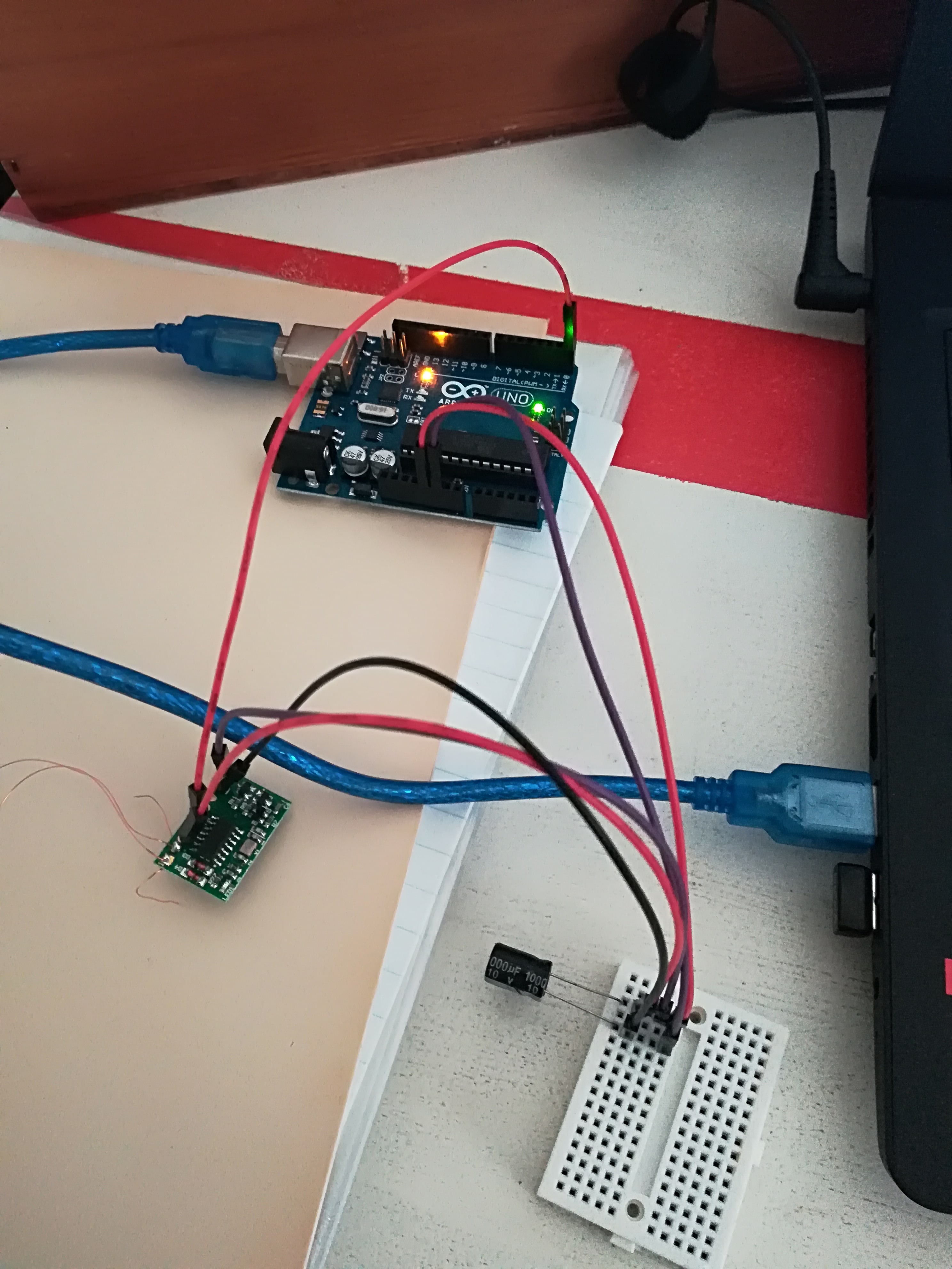
Thanks for the help. ive attached a picture of how ive wired the connections aswell as the code im trying to use. Unfortunately i cant get a read, can you see anything that stands out that im doing incorrectly?
johnwasser:
This setup is using Serial, not Wiegand. The third pin (the one next to the two antenna loop pins) is connected to +5V so it is HIGH. The description clearly describes the pin as "3. high-level election serial port, low-level selection of Wigan, not vacant"
If you are connecting to an Arduino with a spare hardware serial port (Leonardo, Micro, MEGA) then use hardware serial. Otherwise use SoftwareSerial.h. Connect Pin 5 (marked TX on the board) to the RX on your Arduino. I don't see any baud rate specification so try everything from 9600 on up until you receive clear data when a card is detected.
Grumpy_Mike:
But it could be if you wired it up right. It would be the better way to have it wired to the Arduino as it leaves the serial port free.
The fact that the setup wires pin 3 to high means it is not internally connected and wiring it to ground would enable the Wiegand output.
Have you tried other baud rates, as I told you to in Reply 5?
You are clearly not using SoftwareSerial as I told you to do in Reply 5.
Jumper wires don't generally make good connections in pain circuit-board holes. If you want to use jumper wires for everything you should solder female header pins (like on the Arduino) into your RFID card.
I tried the Software serial on pin 9, with the quoted code at baud rates 9600 and higher, unfortunately still no read from the reader.
Is there anyway I can test the reader to see if its working? my soldering isnt the greatest, Im hoping I havent fried the reader.
Will get hold of some female headers and try again. Will also try Wiegand instead of serial.
I found some extra information about the reader, serial number SM-WL125 (see attached picture), seems to be 9600 baud rate.
#include <SoftwareSerial.h>
SoftwareSerial mySerial(9, 10);
void setup()
{
mySerial.begin(9600); // Setting the baud rate of Software Serial Library
Serial.begin(9600); //Setting the baud rate of Serial Monitor
}void loop()
{
Grumpy_Mike:
Look on the TX pin of the reader and see the voltage level and also if there is any activity with an oscilloscope.
So you should be able to get hold of one.
I managed to sort it out, turns out I did fry the reader. Ive managed to get the reader working by soldering the headers to it.
Is there a way I can add code to time for how long the rfid tag is within read range of the reader? ie time for how long the rfid reader voltage is high
DuncanWilliam77:
Is there a way I can add code to time for how long the rfid tag is within read range of the reader? ie time for how long the rfid reader voltage is high
The datasheet seems to indicate a 2.7 kHz square wave appears on the 'buzzer' pin when a card is present. It is not clear if the signal continues until the card is removed. If it does, you could use that signal. Is there a LED on the board that lights up (and stays lit) when a card is present? You might be able to tap into the signal that drives the LED.
Is there a way I can add code to time for how long the rfid tag is within read range of the reader?
I would say not. This is not a normal function of a reader, it could be done but is hardly ever implemented. I once had a customer request to do this, and I did it but it requires custom software inside the reader. As I was at a company that designed and made readers this was not so hard. But in my experance this is not normally what is wanted.
johnwasser:
The datasheet seems to indicate a 2.7 kHz square wave appears on the 'buzzer' pin when a card is present. It is not clear if the signal continues until the card is removed. If it does, you could use that signal. Is there a LED on the board that lights up (and stays lit) when a card is present? You might be able to tap into the signal that drives the LED.
There is an onboard LED, but it only flashes once a card is first detected.
Grumpy_Mike:
I would say not. This is not a normal function of a reader, it could be done but is hardly ever implemented. I once had a customer request to do this, and I did it but it requires custom software inside the reader. As I was at a company that designed and made readers this was not so hard. But in my experance this is not normally what is wanted.
And what about a while loop with some sort of delay? say every 5 seconds The loop tests to see if that card is still "available" and records a time stamp of sorts.
And what about a while loop with some sort of delay? say every 5 seconds The loop tests to see if that card is still "available" and records a time stamp of sorts.
No the code will be sent only once when the card is first presented, if the card is held against the reader the card's number is not repeated.
Again this was a "special" request I also implemented for a customer, but it is not the way RFID readers normally behave.
The chip that implement most Mifair RFID protocols has "card present" signal inside them and that could be used, but I don't think you have that sort of reader and you certainly can't reprogram the reader's software.
Grumpy_Mike:
No the code will be sent only once when the card is first presented, if the card is held against the reader the card's number is not repeated.
Again this was a "special" request I also implemented for a customer, but it is not the way RFID readers normally behave.
The chip that implement most Mifair RFID protocols has "card present" signal inside them and that could be used, but I don't think you have that sort of reader and you certainly can't reprogram the reader's software.
Yeah unfortunately i dont have the Mifare readers. I was advised about maybe restarting the reader every few seconds. would the reader read the card again once restarted? If so can this be done automatically using code? maybe switching off and on the 5v pin
would the reader read the card again once restarted
Probably.
If so can this be done automatically using code?
I don't know.
maybe switching off and on the 5v pin
That might do it, although it is possible that the reader could wait until a card is out of the field before continuing with it's initialisation. Some readers use the turn on time to set calibration parameters to counter effects of local metal fittings. But a reader could take 1.5 seconds to actually read when first switched on. Their are so many unknowns with the reader.
Grumpy_Mike:
Probably.
I don't know.
That might do it, although it is possible that the reader could wait until a card is out of the field before continuing with it's initialisation. Some readers use the turn on time to set calibration parameters to counter effects of local metal fittings. But a reader could take 1.5 seconds to actually read when first switched on. Their are so many unknowns with the reader.
Thanks once again for the insight.
Can i use pinMode and digitalWrite functions to toggle on and off the 5v pin? or is there a better way to do it.