Hi evryone,
I'm looking for help because i want to creat a ribbon cable tester.I'm stuck in the modeling of the board. I wanted to know if I could have some advice regarding the connection between the different elements. I can't understand how to connect the resistors, is it before or after the ribbon? The board will be powered by 5V via a battery or an external transformer. And I want each pin of the cable to be tested individually. I'm attaching an image of what I've already been able to do.

See the many links in Related Topics below.
Why do you want to use so many headers?
Hi DrDiettrich,
Thanks you for your reply.I have read the other topic but none have a scheme or an image. I use different header Because i want to test different size of cable.
Can't you align smaller cables to one end of the biggest header?
What kind of errors do you want to detect?
In the simplest case it's sufficient to connect one end of the cable to I/O pins with INPUT_PULLUP.
1 Like
Been there and done that! I hope you are using standard connectors for both ends so there is NO chance of shorting any two wires together!!!
So what remains to test at all?
That the insulation displacement pins actually did their job!
1 Like
- Unless you will be making several of these, suggest you use wire wrapping to make this tester.
If this is the only problem then all pins on one side can be collected into one input, the other end to individual I/O pins.
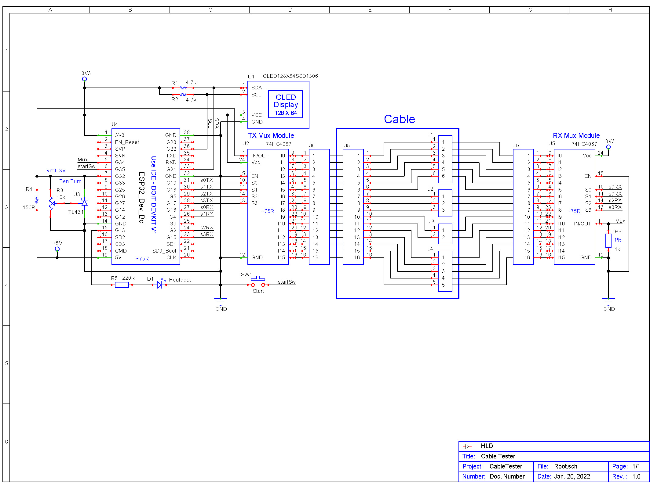
My plan was to make a board like this one:

But make a universal tester board (molex, jamma, 2.58mm,....). I want to make it the more simple possible so i can test very quickly is there is a short in the cable or if the connector have enough grip to do the connection.
Thanks of your help i know now i need a 9v battery but my main concern is regarding the resistor, i don't now if it need to be placed before, between or after cable connector..
Why that?
What's the purpose of that resistor(s)?
Change the design to use a single battery and you can remove the resistors from the design. The LEDs won't be a full brightness but they won't burn out either.
That is exactly how I did the tester to verify the many ribbon cables we made for a customer. Many different cable widths, led and series resistor for each wire. Tester powered by common 12 volt PSU. All cables good. Customer even bought the test unit. No Arduino!
1 Like
would the traces get shorter if you turn the headers by 90 degrees?
Maybe keep all traces from one side at bottom and all traces from other side on top? Or even pin numbers at top and uneven pin numbers at bottom? That would leave more space for thicker traces and less chance of soldering 2 traces together...
If you heat the board too long, the tiny traces will easily come off...
This topic was automatically closed 180 days after the last reply. New replies are no longer allowed.