I'm a noob trying to make a bed occupancy sensor as my first electronics diy project but not getting any readings from the sensors .
I think this might be because the HX711 amplifier board I am using is different from the hx711 in the scheme I followed so I need some help with changing the outputs .
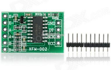
My version of the Load Cell amp (hx711) has DT and SCK instead of DAT and CLK so I'm guessing the output should be different ?
I basically followed the scheme and just wired DAT as DT and SCK as CLK, what should the outputs be instead considering my inputs are are E+, E-, A+, A- ?
The way I have it wired shows me the output in the serial console but no readings :
Initializing scale calibration.
Please remove all weight from scale.
Place known weights on scale one by one.
Reading: 0.00kg
Calibration Factor: 2400
Reading: 0.00kg
Calibration Factor: 2400
Reading: 0.01kg
Calibration Factor: 2400
Reading: 0.00kg
Calibration Factor: 2400
Reading 0.00kg
Calibration Factor: 2400
Not sure if the fact I'm not getting any readings is because I need to rewire for my HX711 board (different from the sparkfun one) or because there is some issue with other wires / soldering .
For stability/protection, you need a HX711 board with two power connections.
With VDD (digital part) connected to 3.3volt, and VCC (analogue part) connected to 5volt.
The 3.3volt connection in the Fritzing diagram is missing, and the green board does not have it.
The green board is designed for 5volt logic Arduinos only (the WeMos is a 3.3volt logic board).
I think only Sparkfun sells multi-logic 3.3volt/5volt HX711 boards (the red board pictured).
They also have connection diagrams on their product page.
If you can solder, and are good with diagrams/datasheets, then you could try modding that green board to the Sparkfun diagram.
Leo..
@Wawa thanks for the input but I don't think the lack of 3.3v is the issue here, as in the original guide I am following it is also not used .
Here is a quote from the guide :
Once you have that, we need to wire the HX711 to the our Wemos D1 Mini (or whichever board you are using). Wire the 5v output of your board to the VCC pin on the HX711, do the same with the ground pins. Then we take the pin labelled D4 on our board and wire it to the DAT pin of the HX711. Finally, RX pin of our board goes to CLK of the HX711. We are using pins 2 and 3 in our code which corresponds to D4 and RX on our ESP board (GPIO 2 & 3).
What I did was use DT and SCK instead of DAT and CLK so my main concern right now is whether the wiring is correct this way, and if not, how should I go about it considering I have the regular hx711 load amplifier .
On a side note, I have 0 experience with electronics and soldering, this is my first try at a diy electronics project .
Triptonpt:
I don't think the lack of 3.3v is the issue here, as in the original guide I am following it is also not used.
Didn't say it was.
5volt logic from the HX711 into a 3.3volt MCU pin is just bad practice, and can damage both devices.
Running the green HX711 on 3.3volt will solve that, but then you have instability from the low/unreglated excitation voltage.
Another mistake on that site is the unconnected VDD of that red module.
Read the Sparkfun page.
Leo..
Wawa: This guide?Didn't say it was.
5volt logic from the HX711 into a 3.3volt MCU pin is just bad practice, and can damage both devices.
Running the green HX711 on 3.3volt will solve that, but then you have instability from the low/unreglated excitation voltage.
Another mistake on that site is the unconnected VDD of that red module.
Read the Sparkfun page.
Leo..
Thanks I appreciate the hints and will take that into consideration, but right now I need to know if my wiring is correct !
And yes, the guide you mentioned is the one I followed !
So right now I have DT to D4 and SCK to RX .
Would this theoretically work ?
I get 0 readings but need to know if that's from wiring it this way or if it's just an issue with the soldering somewhere along the circuit .
Add some data logging and you know what she's doing in bed - and an alarm when the weight is significant more than hers but you're not at home (do allow some weight for the cats to jump in with her). You have up to 3 MB SPIFFS for writing logs!
Triptonpt:
So right now I have DT to D4 and SCK to RX .
Beware of the pin use:
Rx = GPIO3, one of the Serial pins and connected permanently to the USB/Serial interface chip.
D4 = GPIO2, this is involved in the boot process. Use with care.
The other pins:
Tx = GPIO1, one of the Serial pins and connected permanently to the USB/Serial interface chip.
D3 = GPIO0, fixed external pull-up as it's involved in the boot process. Use with care.
D1/D2 are the defaults for SCL/SDA (I2C) and can be used as regular pins if you don't use I2C.
D0 = GPIO16, no interrupt, internal pull-down (no pull-up). Could be connected to the RESET (NodeMCU does this).
D5-D8 are the SPI interface; can be used as regular pins if you don't use SPI.