I cut a couple traces on the back and soldered some small jumper wires so that i can go into and out of the headers on it. I will post a picture of that later today, I am at a library far from home but i have my arduino with me,
When i get back to utah i am simply going to solder one of these into the middle of a four lead jumper cable:
i believe you are correct. also the rs232 module we have, that unused header on the side is for the other serial control lines.
unfortunately arduino serial and softwareserial only implement rx and tx. it would be really nice to have cts (or would it be dsr?) because when the display processor is busy the input buffer, atleast on gu7k, is only 12 bytes.
there are some other ways to get the job done in the mean time while you wait.
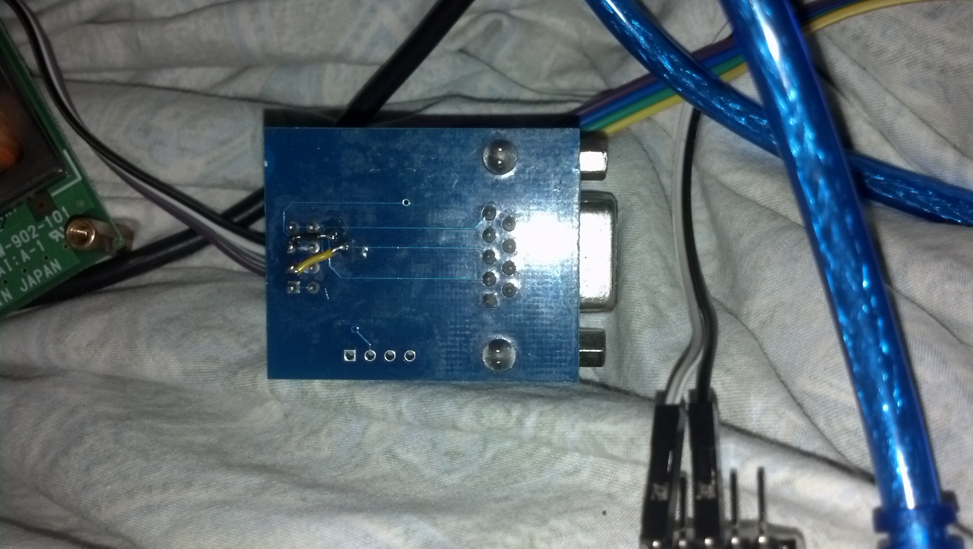
if you can source some basic transistors or logic chips in brazil there are some cheap ways to do the voltage conversion. attached are a couple schematics, and a picture of my modified rs232 converter. i cut traces between the extra rx and tx pins and ran small wires from vias (tiny solder holes) in the board that are attached to the traces that go to the db9.
correct you can drive this with 3 wires - vcc, gnd, and tx.
the hazard is that some commands cause the display processor to be unavailable for new input for a short time, so you may notice text truncated after a command or possibly complex commands failing.
for example if my gu7k is configured for 38400bps serial, the command to alter the brighness of the display must be followed by delay(5); or else the following text is truncated at 12 bytes.
it would be very helpful if we had dsr/dtr but this will require rewrite of the softwareserial library.