I am having a hard time soldering a BOO085 IMU IC onto my PCB. It is so small, that I accidently either short it somehow, or dont get a good enough connection for stable communication.
The PCB works, Ive gotten short bursts of data output from the BNO085 gyro data, but then the device has been “reset”. And I am pretty sure its the solder connections
I have an idea, which Id like to ask the proffessionals!
It feels like when I solder (reflow) U2 that all or a lot at least of the excess solder goes “out” from underneeth the component, and its easier to remove the excess solder with a solder wick.
I am not sure what the question is. As far as alignment, the pins will snap to the pads when the solder melts. I assume you are either using a hot air gun or an oven.
When I have to resolder those QFN’s I use a lot of liquid flux first, then I drag-solder the qfn footprint on the PCB, so that every pad has a tiny bit of (I use leaded) solder. Then liquid flux again and I drop the component in place. Then slowly heating it up so that the IPA from my flux evaporates first and only the rosin is liquefied. The evaporation creates a lot of bubbles that instantly misalign the part. So when the bubbles are gone I heat it up with the hotair soldering gun at 300C, until I see the solder flowing and the part shifting downwards in place.
I know that 300C is a lot of heat and probably more that the datasheet allows for, but with lower temp I can’t get it to work. I use low temp leaded solder as with leadfree I tend to need even higher temps to get a good flow.
i use a no clean solder paste designed for SMD components, it is a bunch of very tiny solder balls in flux. It comes in a syringe and I use the appropriate dispensing tip. It has a shelf life and I keep it in the refrigerator when not in use. I place that on the pads and heat with hot air and it works great. I do not know what the flux is but it is not rosin. When finished I clean with hot water and soap followed by a rinse. Here is a picture to give you an idea of what it looks like.
I use two magnets either side of the board to hold the chip in place , then solder a couple of corner pins .
Wipe the pins with flux then wipe a lightly loaded soldering iron across. You can do this with a small chisel tip iron
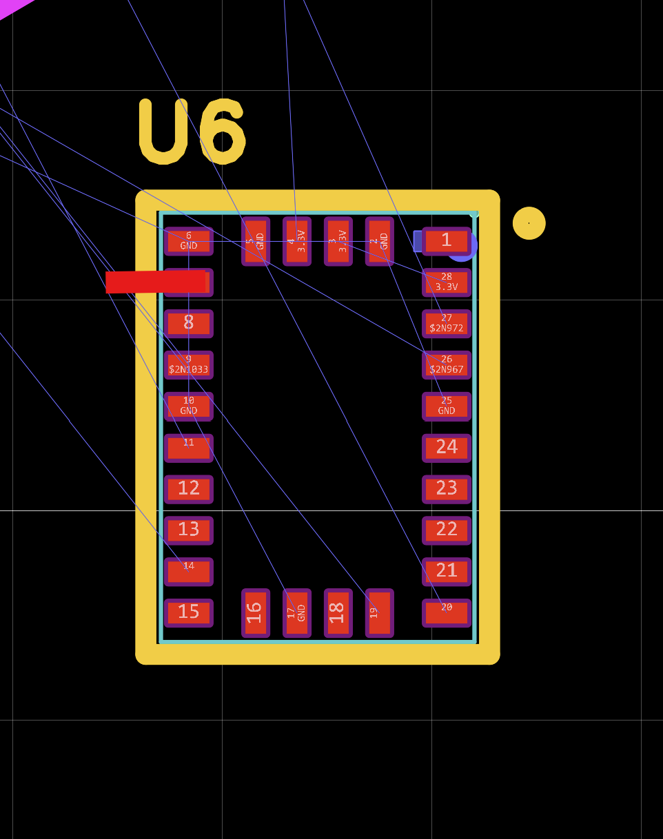
It probably aligns pretty ok, but its hard to verify that it is really good, and also that there is not to much solder on each pin so that they short, my question is if it could work to rework the footprint of the pads like this:
Is that the excess solder paste usually gets “pressed” or somehow gets “out” from underneeth the component, and then can easily be de-soldered with a solder wick.
But im not sure that that is a very good idea.
I think I have this today, but since it is so small its hard to pour just enough solder paste and feels like I always get too much paste on the pads, but I will look into some smaller “needles” for the tube, maybe now when I think more is the cause of the problem, I will look into some smaller needels too.
This sounds like a good idea, but its also hard to align when you cannot see the pads or “pins” when every millimeter kind of counts
I will give a smaller needle a try I think, or maybe try to re-size the pads if you think its an ok idea
I just use a very fine soldering iron tip on a temperature (digital) controlled iron.
Liquid flux, sometimes home-made or a commercial product like Chip Quik SMD.
Get solder on the pads first and clean up with copper desoldering braid.
Enough solder is left for good joints.
Chip Quik is sticky enough to hold the chip in place.
Dab each pin with the tip of the soldering iron with a small amount of fresh solder to get good thermal contact.
Examine at each stage under a magnifier. Cleanliness essential. Rub over with propanol.
Seems to work, never used hot air gun or oven.
Learnt over the years just how fragile these little pads are.