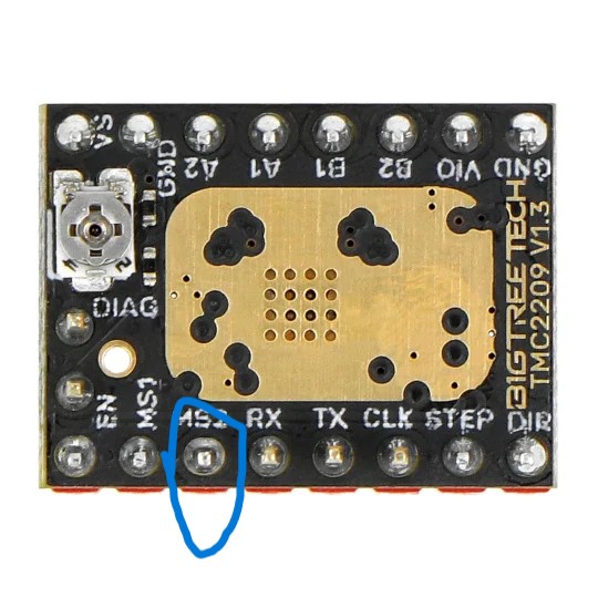
The microstepping pins MS1 and MS2 use every combination of VCC and GND, so those two pins could not have been "mis-wired"
The only way to find what is happening with the issue is to honestly tell the whole story between "it worked" and "it does not work." Go through the physical motions, the programming motions, and whatever else you did, with the motor, with the driver, with the sketch... and you will find the answer. You can flag this post for being "offensive" just like @jreebel did when I pointed exactly to where he would "find" his missing hardware, but stuff happens, people make mistakes, and you have to own up to the fact: Only you touched it. That other user blamed the manufacturer for sloppy, negligence, then blamed me for breaking into his house (it couldn't have been for keen observation - that's not breaking rules), then had my post taken down, and if I can see the future, will keep taking down honest posts.
I will guess that the microstepping selected by the potential on the two wires made the motor require more power that was available from the power supply.
I am trying to build a project using a stepper motor. I have a Usongshine Nema 17 and a TMC2209. I had the whole setup working but now it doesnt work anymore. Right now, when I just have it spin the stepper, it works fine until I connect the microstepping cables to 5V. Then it completley stops spinning and even when I unplug the the stepper stays very jumpy.
To troubleshoot microstepping issues with the TMC2209, ensure correct wiring and microstepping settings via MS1, MS2, and MS3 pins or UART mode. Adjust the motor's current limit using the VREF voltage for optimal performance. Test the motor movement and consider switching between StealthChop and SpreadCycle for smoother operation.
The "MS3 pin" on the TMC2209 is typically used for controlling the microstepping mode, but in many cases, it is tied to "logic low" or "high" to select different microstepping resolutions. The setting for MS3, along with MS1 and MS2, determines how finely the motor steps.
and (UART (Universal Asynchronous Receiver/Transmitter)) mode is a communication protocol used to control the TMC2209 stepper driver. In this mode, you can configure various settings, including microstepping, current limits, and more, using a microcontroller (like an Arduino or Raspberry Pi) that communicates via serial (TX/RX) pins.
Can work 5-28V?
I expected 5-28V for the motor not for the logic...sorry but i don't want fire the board EVAL immediately.
I must connect a motor to 12V..so about the STEP it needs 0-12pk-pk, or also 0-5Vpk?pk. Sorry i'm a little confused.
MS1-MS2 not connected (pull down resistor) it obtains 8 microsteps