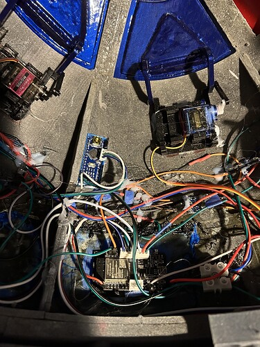
I have an arduino nano inside an r2 d2 dome (printed) with a led matrix sketch. Basically 5 matrix chained driving random leds. Also inside the dome are various other things, one involves a high voltage output cylinder( basically a taser) which runs from couple aa size batteries triggered from a relay remotely via esp32 and blynk app. Everything moves and does what it’s supposed to except when the taser is triggered, the led matrix starts to shut down and leds turn off. There is only 3 pins used on the nano driving the matrix. I assume the analog pins are floating or something. Ive tried defining them as an input pullup to stop them floating or interrupting the sketch but its not working. Is there anything else i can do, bear in mind that everything is mounted and already in place so heavily modifying the board could be difficult.
Photos of the layout and a schematic showing power, grounds etc.
A schematic would be hard as u can see there are alot if wires. But basically an 18v drill battery supplies power to everything except the taser. All grounds are connected together at the point of ingress and power goes to 2 different buck converters to get everything at 5 volts. The nano buck supplies the nano and power for the matrix. The other supplies the esp32 and the rest of the electronics.
Taser r2 - Google Drive Here is a link to a video of it.
common problem when switching hign voltage/high current devices using Microcontrollers - sometimes can even reset the microcontroller
some ideas
- make sure all metal is earthed
- put the micocontroller in a metal enclosure
- connect microcontroller to external devices using shielded cables (earth the shield)
So basically a makeshift faraday cage earthed to the main ground power?
havent used an actual Faraday Cage for some years but that is the idea
the majority of systems I use are industrial and in metal enclosures for physical protection as well as acting as a electromagnetic shield
however, you then have problems if your WiFi, BLE and modems are inside the enclosure
sometimes will work with limited range otherise have to run out to external antennas
Well the good thing about that for me is the nano is standalone with no wifi or anything. Runs simple code.
Actually the aa battery ground is not connected to the main power. Would running the gnd from there to the main power effect the voltaGe or have some other side effects?
The hv arrangement you have there along with any associated wiring is going to blast everything within cooee with rf noise.
I'd be looking at some other way to produce a "simulated" taser (or whatever it is) as you will certainly have an uphill battle trying to keep your micro isolated .
Its in, im thinking more along the lines now of resetting the nano when it switches off. By using a low signal from esp to pull down the rst pin on nano.
Hi,
Regard EVERY bit of wiring connected to the Nano as a receiver antenna.
Regard EVERY bit of "tazer" wiring as a transmitter antenna.
Can I suggest you take your DMM, put it in AC volts mode, 600V range and just snake the leads through your project, do not short the leads or connect them to anything.
Activate the "tazer" and note the readings.
Tom... ![]()
![]()
![]()
![]()
@tezzatron81
It may not be the nano that's at fault
It looks like you have a serial interface between the nano and the matrixes.
Clock
Data
Load
They are probably picking up the EMI.
Try putting a 4.7K pull-up resistor on each of the lines.
All those loops of wire are just what you need to pick up an transfer interference all over the place, not at all surprised you are having problems.
Circuits are called circuits because the current has to circulate from the source, through the wires then back to the source. First rule to minimise interference is to ensure that the wire carrying the current to the load and the other wire carrying it back are physically close to each other, as in a cable. No individual wires like you have plenty of. This applies both to circuits that might pick noise up and circuits that might generate it.
Next is to be careful of wires that carry ground current because wires have resistance, which generates voltage when current flows through them. One wire carrying current from two different loads will generate voltage from one load that will interfere with the other. You address this by giving each load its own return path (wire) and making all of them common at a single point.
I tried and only seen like a 1, I’ve obviously done something wrong. I will try the pull-up resistance suggestion next, and then ill just probably reset the nano
This topic was automatically closed 180 days after the last reply. New replies are no longer allowed.

