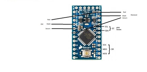
I am going to solder wires going from my SainSmart 1.8" TFT display to my Arduino Pro mini. When I connect this display to my arduino nano I connect the SCL and SDA pins to digital pins 13 and 11 but I see on the Arduino Pro mini there are two pins designated for SCL and SDA. So I am confused as to where I am suppose to connect them.
Use any. (pins marked 13 and CLK is the same line)
I soldered it using these connections CS-10, Res-8, RS/DC-9, SDA-SDA, SCL-SCL, and I hooked up the vcc and ground correctly, but when I uploaded the program I just get a white screen.
Pretty much anything with "CS" as an input is likely to be SPI. Therefore clock and data need to be the SPI pins, not the I2C pins. Try SDA-MOSI, SCL-CLK.
Something like the ADXL345 accelerometer chip can do both SPI and I2C, but the name of the pin can only be one or the other, so they chose SDA and SCL even though they are used as MOSI and CLK in SPI mode.
Thank you so much! ![]()
