How can I use an Arduino to control an IGBT DC motor controller?

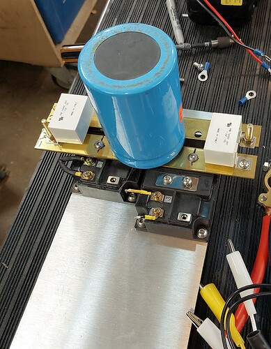
Hello, I am working on converting an old Volvo to full electric, using a repurposed forklift traction motor. I have been following Damien MaGuire's lead on his Youtube channel (where he converted a BMW for 1000 Euro). I have built the power stage using 2 large IGBTs and capacitors, and the assembly does turn power on and off when I manually load and unload the gate on the IGBT.

That leaves the portion that supplies the logic to turn the IGBT on and off in pulses. I thought an Arduino might be a good choice since they are used to control small motors, but I realized the motor controller boards are actually shunting the big power -- they are not sending successive pulses of +12v and -12V to turn the gate on and off.

I'd still like to use the Arduino, since the coding looks so simple and elegant, and I'm sure I can come up with something that will work-- once I get the hardware sussed.

So, what sort of chip or controller should I use in conjunction with the Arduino to give the +12v/-12V pulsing needed to cycle the IGBT?

Thank you.
Hi!
Working as the designer for the control stuff, computer and more, on electric fork lift trucks I ought to be able to contribute.
The really old traction motors were of the brushed motor type. Right?
You really need a hefty inverter to PWM control such a motor. The start current can be anything from 3 to 4 hundred amps up to 1000.

Wrong! It's al about the inverter handling the big current. The low voltage control is not much of a problem.

Minus 12 volt surprises me. Handling +12 volt is easily done using a transistor.

Could You post a link to the datasheet of the IGBT?

My first thought was the gate drive needed to switch those huge currents on and off without blowing up the IGBTs.

Next problem would be managing the shoot through on an H-bridge.

@thaddeusthebold : Arduino isn't an "elegant" solution to this. It could be a solution, but I think you have a lot of engineering ahead of you and the CPU you use won't matter much. That said, I'd aim for a microcontroller that has build in high side/low side PWM that is designed to control an H-Bridge. Life becomes much easier if you can handle that stuff in hardware. I think a black pill should have the PWM features you need here.

Can You post a link to the datasheet of the inverter?

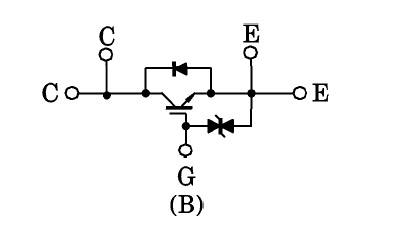
The data sheet for the IGBTs I am using is attached here. One is switching, one is acting as a freewheeling diode. Thanks all!

Just posted the data sheet on my website here.

The IGBTs are Toshiba MG600Q1US41's.

What is a 'black pill'?

Hi,
You will need to use a driver IC to control those IGBTs, you need to drive against the gate capacitance and high enough voltage to turn the IGBT fully ON.

Can you please post a schematic of the assembly in the image you posted in post#1.
What is the power/voltage specs of your motor, can you post a link please?

What did the YouTuber use to control the IGBT assembly.
You will have to do current control, regen control, fault detection.

Thanks.. Tom... :smiley: :+1: :coffee: :australia:
PS. can you please post a link to the starting YouTube video?

TBH, I think you'd be better off using a prebuilt motor driver like this one

[edit]
That's an example. It's likely too small for what you're doing.

This is what I have built so far. I can turn power on and off to my little test motor.

The person who I got the idea from is here:. I altered things some, based on another bit of reading I did (using slightly different IGBTs, based on availability). MaGuire has a controller board design available, and I even downloaded it and had some prototype boards made for cheap in Hong Kong... but when they came, they needed the little teeny tiny board components, and there was no way I was going to be able to solder them in. So I went looking for another solution.

Which brings me here.

Hi,
Your "circuit does not make sense, what is the need for the right hand IGBT in the circuit?
If you turn it ON, it will short the motor, if both are truned ON you short the battery.

Where is your fuse in the battery line to protect yourself and the hardware?

PLEASE use circuit symbols, here is the IGBT symbol in the data sheet.
igbt

This can all fail dramatically without some proper troubleshooting tools and a proper schematic is essential.

Tom... :smiley: :+1: :coffee: :australia:
PS. Please define "Huge Capacitors", they should be in your schematic.

1 Like

Hi,
Here is my interpretation of your project.


Q2 will control your speed, but what will Q1 do when it is turned ON.
I can see you might be using it as a dynamic break, but the IGBT will not just have to withstand the braking current from the motor, BUT the fully charged capacitors.
The motor will have some maximum current when breaking, BUT the capacitors will want to dump ALL their energy at once through Q1.
You will have to throttle Q1 very carefully when operating it.
In fact you are going to need some current monitoring components to prevent things like motor burn out or shorting.

As I mentioned earlier you will need a gate driver IC to control the gates.

Have you done any calculations on these currents?
I assume the motor is connected to the existing gearbox, so you still have reverse gear.

Can you please tell us your electronics, programming, arduino, hardware experience?

Tom..... :smiley: :+1: :coffee: :australia:
PS, What do you mean by a "precharge contactor".

1 Like

Q1 is intended for use as a freewheeling diode. The place I got the idea is here.

I have not done calculations on the currents.

The motor will be attached to a manual gearbox.

My electronics experience is limited to a HAM license, and I have repaired a few broken tube radios to functional state. (Kenwood 520S, Yaesu 101, SWAN, Drake).

Programming experience is limited; some PERL, GCODE for my home-built CNC machine. My code is ugly but it works.

Hardware? I build everything from acoustic guitars to mechanical clocks to electric tricycles to buildings. I've restored Porsches and rehabbed houses. I'm handy and curious.

So: I admit this is maybe my hardest venture yet, but I'm learning.

Leaving aside the current monitoring components for the moment,

I had an idea on how to trigger the PWM control on Q2.

The Arduino can control 2 motors. yes?

So... if I use the control for motor 1 to trigger a MOSFET to deliver 12VDC to the gate such that A is positive and B is negative,

and then I use the control for motor 2 to trigger a MOSFET to deliver 12 VDC to the gate such that A is negative and B is positive,

Then write the Arduino code such that the controls are run successivle,

I should get the effect of successive +12VDC and -12VDC being delivered to the gate.

Might that work?

Hi I"m not sure what you are trying to do, if Q2 is the IGDT that will control speed, then use a driver IC, such as shown in the link you showed me.

What TWO engines?
You do not need +12v then -12V delivered to the gate, just +12V and 0V, that is if your IGBT is happy with 12V gate voltage.

Tom.... :smiley: :+1: :coffee: :australia:

If it's happy with 12V and 0V, then my whole question is moot. I read in some places that IGBTs required negative current to be applied to turn off - + 12, then -12.

I guess I should mock it up and test empirically. With baby voltages, of course, since I don't want to die or anything.

So, successive bench tests show: +12v to start the motor, ground the contacts to stop it. I.e., 0V.

You aren't likely to die, but without a proper gate drive to those transistors, you will see a lot of smoke and likely flames!

OK, I think I have figured out how to control the IGBT. I have ordered a HCPL-3120 unit.

Looks pretty simple to wire, should be controllable by the PWM signal from the Arduino.

I have to throw some resisters across some of the pins, according to the spec sheet, and no idea how to size those... but at least i'm one step closer.

Thanks for all the input folks, driving me towards progress. Much appreciated.

This topic was automatically closed 180 days after the last reply. New replies are no longer allowed.