The details don't say what the stall current is, but the rated current is 50mA, the rated power 3W, which
means something is wrong. If its 3W (more believable), that means 1A or so running current, significantly
more stall current. This means it cannot be run from the Arduino 5V (a bad idea anyway to share supplies
between motor and logic)
But its only wants 3V or so, and most supplies tend to be 5V or 6V.
I suggest using a darlington transistor (like TIP120) which drops a volt or too, and an external 5V 2A supply or similar. 1k base resistor into a darlington is probably fine.
As its an inductive load a free-wheel diode is needed - google for Ardiuno motor and relay circuits to see
what's needed.
MarkT:
The details don't say what the stall current is, but the rated current is 50mA, the rated power 3W, which
means something is wrong. If its 3W (more believable), that means 1A or so running current, significantly
more stall current. This means it cannot be run from the Arduino 5V (a bad idea anyway to share supplies
between motor and logic)
But its only wants 3V or so, and most supplies tend to be 5V or 6V.
I suggest using a darlington transistor (like TIP120) which drops a volt or too, and an external 5V 2A supply or similar. 1k base resistor into a darlington is probably fine.
As its an inductive load a free-wheel diode is needed - google for Ardiuno motor and relay circuits to see
what's needed.
Thank you for explaining
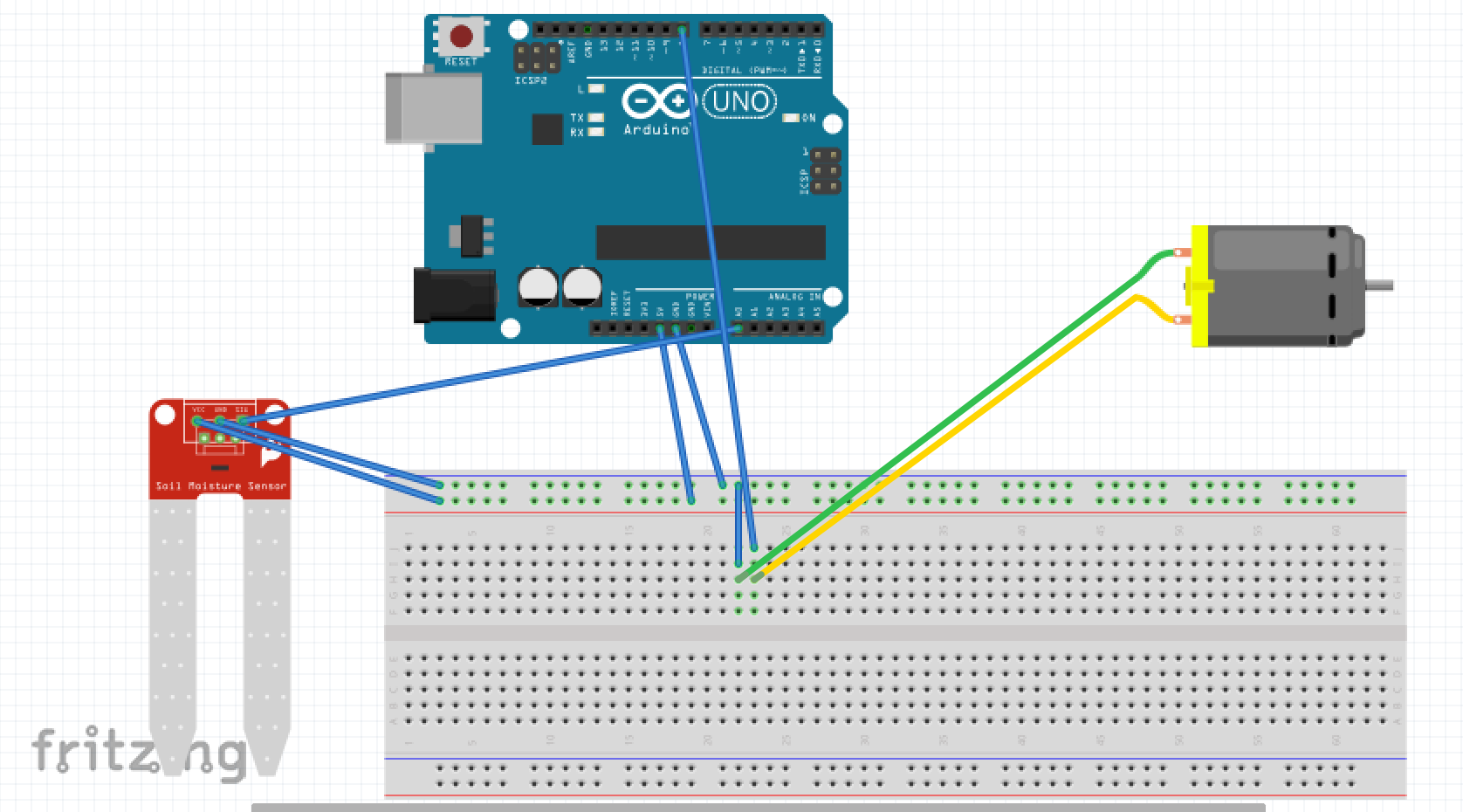
I have currently set it up like this:
Except the DC motor is the pump. It's actually working really well but from what you said this doesn't seem to be the correct way to do this.
So I'm asking what is wrong with my setup and why? I really want to understand why it's wrong to do it the "noob" way I did it.