I have a 12v DC motor and a 12V 5Ah battery, I want to be able to switch it on and off with this relay, but I am confused on how to use it.
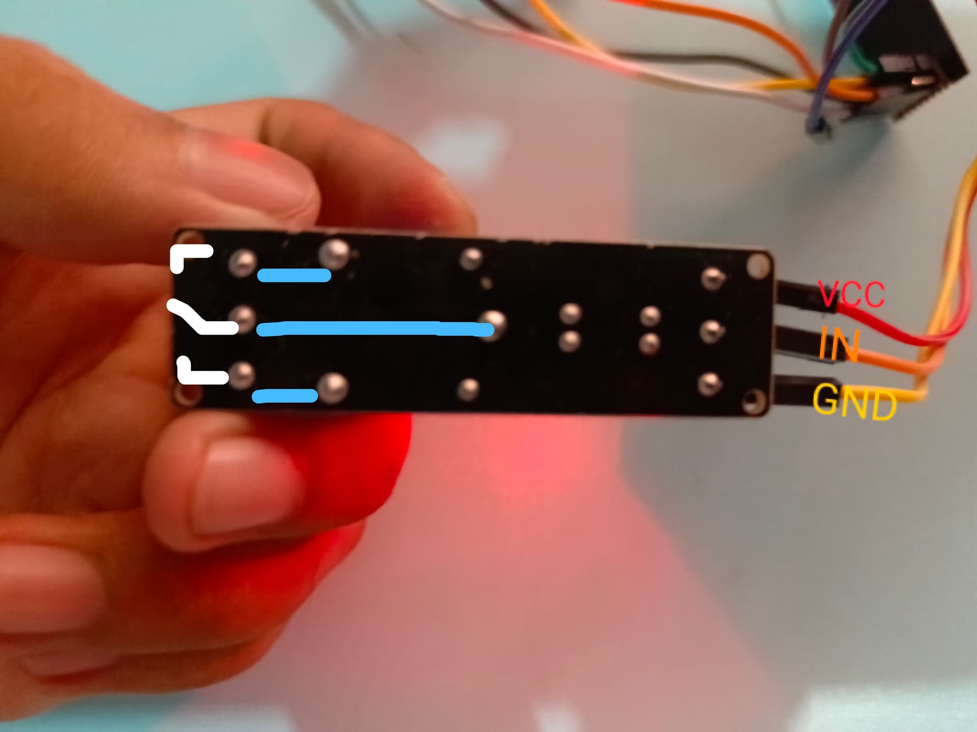
I am powering the VCC pin with 5v.
I power the IN pin with 5V every 3 seconds
(which lights up the green LED on the arrow when powered).
GND is grounded in arduino uno.
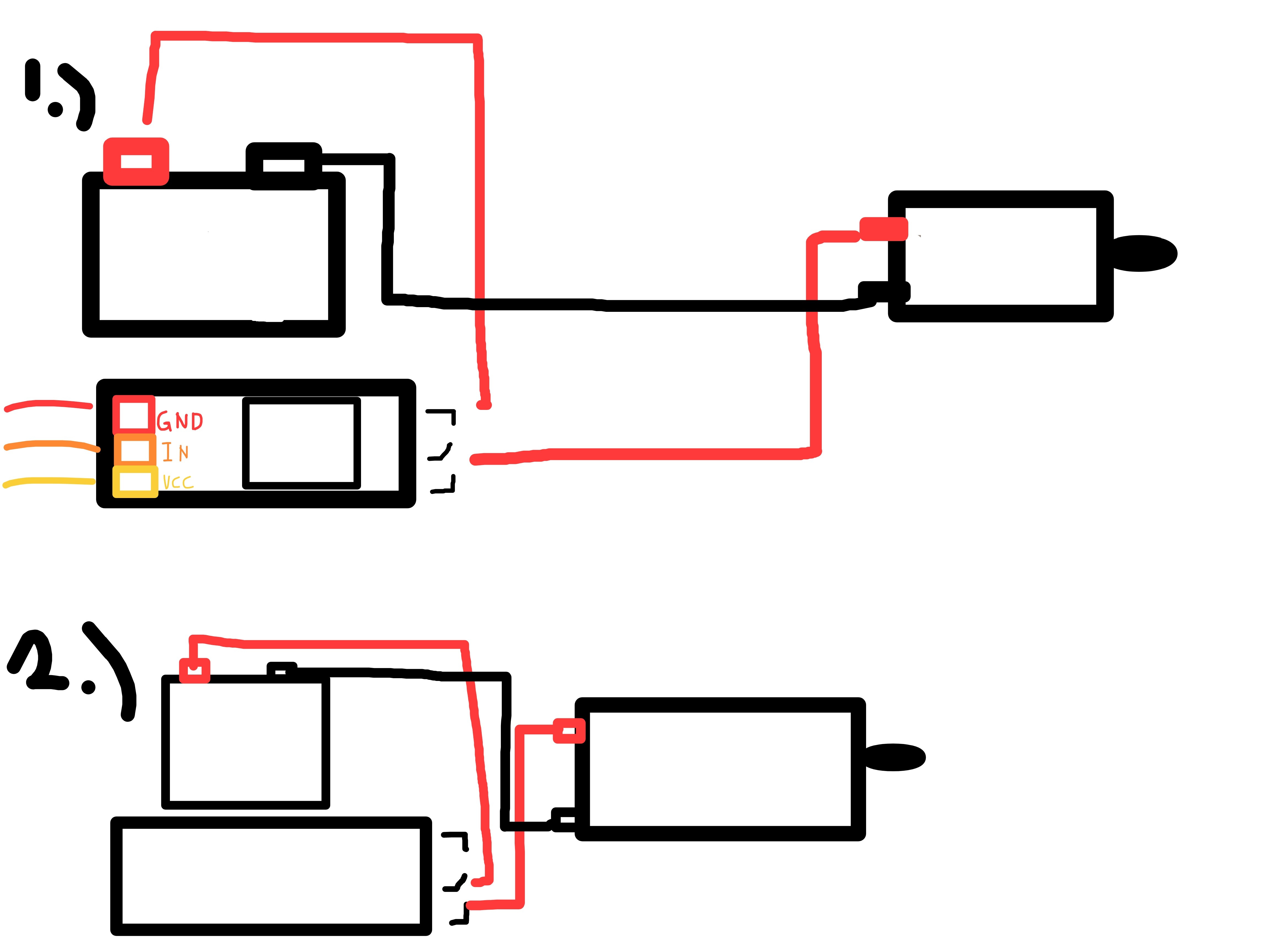
How do I go about using the other side of the relay?
Below was my attempt #1 but nothing seems to change even if the IN pin was powered or not- The motor runs on the NO pins but doesn't turn off even whether the IN pin is powered or not.
On attempt #2, motor is silent even when IN pin alternates between powered and not powered, only the green LED changes.
I've tried poking it with a multimeter on the NO pins when its on continuity, it says 001 when led is on and sometimes 000 when led is off but most of the time, its stuck at 001. Is it broken?
It also doesn't seem to have that "click" sound that i've heard when people used this relay by itself.
The sketch used is below.
void setup() {
  pinMode(2, OUTPUT);
}

void loop() {
digitalWrite(2, HIGH);
delay(3000);
digitalWrite(2, LOW);
delay(3000);
}
Hello keithou
Post the current sketch in code tags to see how we can help.
The relay itself needs 12V to switch. It looks like you're providing it with 5V.
As a first test, I would disconnect the Arduino, connect Vcc and GND to the battery and use a wire / switch from the batteries +12V to the IN pin of the relay module.
Next you will have to find the schematic of your relay module to make sure that the below is safe (I think it will be but I don't want to be responsible for blowing up your Arduino).
- Remove the existing Vcc connection from the module.
- Connect it to the +12V of the battery.
- You need a common GND (GND of battery to GND of Arduino.
This will more than likely work as the optocoupler on the relay module will react on the 5V signal from the Arduino that is connected to the IN pin.
PS
This is a poor choice for the relay module.
Hi, I've tried powering VCC with 12v as well but the green LED doesn't light up when IN is powered by 12v and does not also respond when IN is powered in 5v(while VCC is 12V) either, which is why I've stuck to using 5v in VCC and IN- the only time the green LED in DS2 responds.
Did you have a common ground between the 5V and 12V supplies?
No, I've separated them. I figured that'd be bad. 
@keithou did you read this?
Oh, apologies! I've missed that- I'm using two devices to look at the forums and read yours first.
Hi all, I've decided to just use a proper motor driver. I have an L298N here and i'll probably just use that. I had wanted to use this relay since I only needed it to run at full speed and off but oh, well.