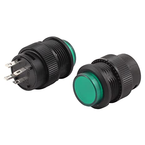
I just purchased this button thinking it could be inserted in a breadboard.
r16-503
I was wrong, I can't insert it in a breadboard. I'm new to electronics and I'm wondering how I can use it. It doesn't appear like it needs to be soldered. How does one properly use these pins?
I keep the cut-off legs from components like resistors and diodes on my soldering desk. When I need short stiff wires to push into a breadboard I will use those.
If you don't have offcuts, buy header pins that come in strips.
Push 4 wires/pins into the breadboard in the pattern you want. Balance the switch on top. Solder the first pin (carefully). Then solder the others. Unplug your newly-pluggable switch and install it whenever you need.
@Loomy, if you have the proper means as those above have suggested, by all means use it. However, in a pinch, I have soldered on a section of a small paperclip. This was only for testing while waiting on the proper hardware to arrive.