Hello everyone, i will start by saying that i am a beginner of electronics and i don't have much experience hence i am making this post asking for advice from more experienced peopled than me.
Now that i have lowered the expectations :)), let me present my situation;
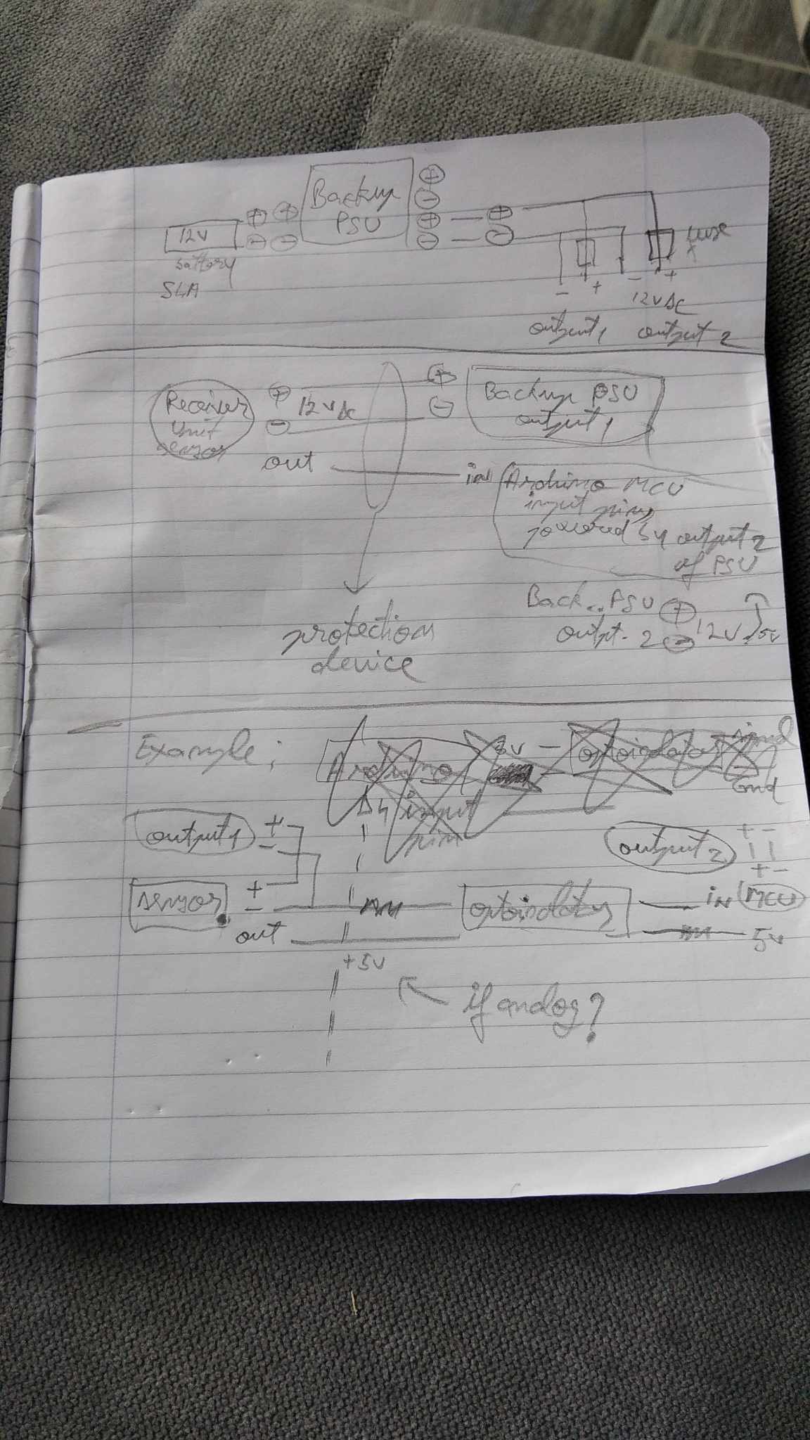
I have a 12v PSU with 12v 7Ah SLA battery backup that has 2 sets of 13.8v outputs, one of them goes into a board with multiple fuses from where i will be powering my electronics. Presented at the beginning of my drawing, i will call output1 and output2, wich are 2 fused output i am interested of using.
Afterwards i have a simple pir sensor wich gets 12v dc for power, and outputs a signal wich must be interpreted by an arduino mcu board. Nothing fancy so far, i expressed that fact that i will give power for the sensor from output1 and power to arduino from output2. The output of the sensor goes into a digital input pin on arduino.
Now i want to make this setup proof to any external interventions of sabotage as an example would be to apply an overvoltage maybe even 230 ac power to any wires that goes into that sensor and try to fry/affect the arduino input pin/psu wich is also powering the arduino.
For that i have into consideration to use some sort of device that will just intrerupt the wiring in case of not normal operation or even fry itself protecting the other components.
What i need is;
A device wich will protect the sensor output line wich get received by arduino IO pins and not fry them. For that i considered an optocoupler.
Considerations; an optocoupler would work for a digital high/low signal that comes from the sensor, on one side sensor high pin and sensor gnd / on the other side arduino 5v and input pin (with corresponding resistors and wiring but that's not my main subject here).
In case of sabotage for that output line i suppose this will do but what if i want to read analog values instead of digital? this optocoupler is only closing a circuit when it have voltage on the transmitter led side letting the 5v of the arduino flow into the Digital input pin.
For the power side, i have purposely powered the sensor/arduino from 2 different outputs to express that i need some sort of protection on the output1 wich is powering sensors, and in case there will be an attempt of sabotage on the sensor ~12v power wires, the device must interrupt the power and protect the psu itself also the other components powered from the same psu but different outputs and keep them running.
For isolation i considered a 12v dc-dc transformer wich only creates a galvanic isolation between sides but has nothing to do with overvoltage protection.
On same topic i would want to ask if transistors can act as separators in case of overvoltage between collector-emitter and just fry if exeded max voltage rating
I am looking forward for any advise, any help would be appreciated!
Regards, Alex!
