To administration: If this is not a suitable place for such an explanation, feel free to move ( or delete ) it.
Here in the forum it happens again and again that people ask for stepper motors for projects and which ones are suitable. The topic of stepper drivers with current control often comes up.
Unfortunately, incorrect advice is often given, which shows that the principles of current control have not been understood. At best, this leads to confusion for the questioner, at worst to wrong decisions.
I would therefore like to try to shed some light on the principles of current control (only simplified, without going deeper into the mathematical calculations). Nevertheless it's a lot of stuff, but maybe someone will read it after all ![]()
( Since English is not my native language, there will certainly be linguistic errors. I hope it is still understandable )
Let's go:
The principle of current control is also described in the A4988 data sheet, for example. However, in order to understand this description, a basic knowledge of electrical engineering is required that goes far beyond Ohm's law. This applies in particular to the behaviour of inductors and capacitors, which cannot be described using Ohm's law. Without understanding the function of these components, it is also impossible to understand the current control of steppers. Therefore, here are a few explanations of these components.
In contrast to an ohmic resistor, which is a consumer and converts electrical energy into heat, capacitors and coils are storage devices for electrical energy. This means that they can store electrical energy and also provide it again. Capacitors store energy as electrical charge, coils as a magnetic field.
The relationship between current and voltage in these components differs fundamentally from the relationship in an ohmic resistor. If, for example, a constant current flows into a capacitor, the voltage increases continuously over time. Conversely, the following applies to a coil: If a constant voltage is applied, the current increases continuously. The fact that this does not go on indefinitely is only due to the fact that neither the current/voltage source nor the real coils/inductances and capacitances are ideal components.
The following applies to a capacitor: The current is the externally specified value, which can also change abruptly. The voltage is the derived value, which is determined by the energy stored in the capacitor and therefore cannot change abruptly.
The following applies to an inductor: The applied voltage is the externally specified value that can change abruptly, the current is the derived value that depends on the stored energy and therefore cannot change abruptly.
N.B. A real capacitor is generally much 'closer' to the ideal than a real inductance (coil). A real inductance can easily understood as a series connection of an ideal inductance and an ohmic resistor. Thats why the coils of a stepper heat up very much.
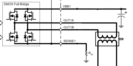
So how does current control work in a stepper motor driver? Essentially, it consists of an H-bridge for each coil of the stepper and a circuit for measuring the current that flows through the H-bridge from the outside. In addition, a buffer capacitor is required at the input of the driver, which is charged via the power supply unit ( and via the stepper coils as we will see later ).
Here is an extract from the A4988 data sheet:
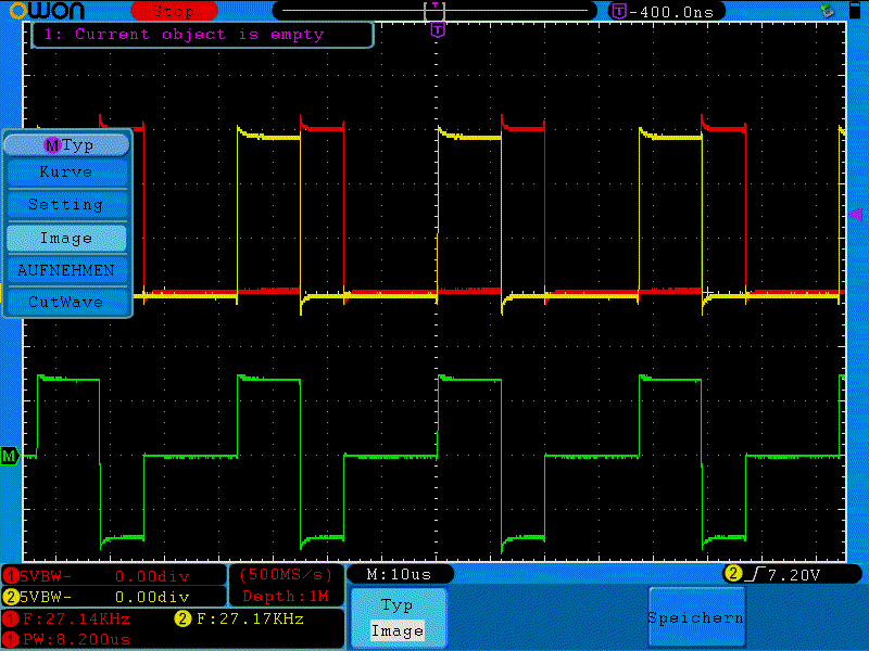
Now let's see how the driver controls the current:
Step 1
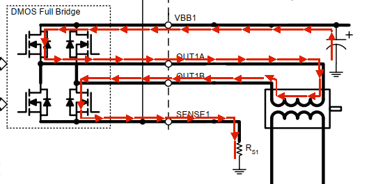
If a certain current is now to flow through one of the stepper coils, the coil is connected to the buffer capacitor via the H-bridge. The full capacitor voltage is now applied to the coil. The current flowing through the coil increases. Ultimately, some of the electrical energy stored in the buffer capacitor is now transferred to the coil. This current also flows through the current measuring shunt, and when the voltage drop at the shunt reaches the set reference value, the H-bridge switches off.
As already mentioned, however, the current through the coil cannot simply be switched off - it continues to flow in any case.
Here the current drivers have 2 modes: 'Fast decay' and 'Slow decay'
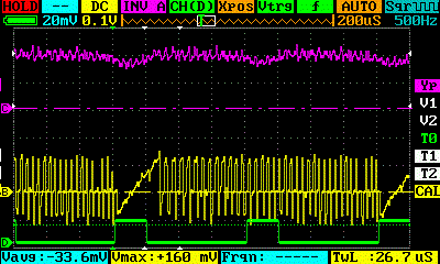
Step 2
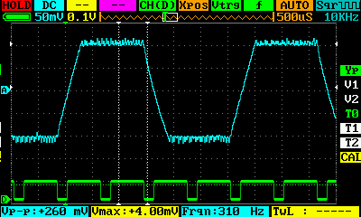
In fast decay mode, the H-bridge is switched so that the current flows back into the buffer capacitor.

The external current flow is reversed - the voltage drop at the shunt becomes negative and the voltage at the coil also changes sign. The coil is now a generator and part of the energy just transferred from the capacitor to the coil is now pumped back into the capacitor. This causes the current to drop relatively quickly ('fast decay'). Current measurement is no longer possible, which is why this mode is time-controlled (approx. 10µs for the a4988).
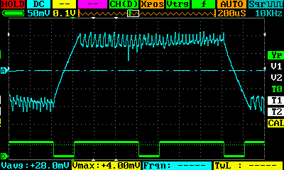
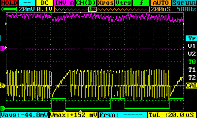
Step 3
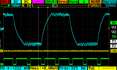
After this, the system switches to 'slow decay'. The coil is short-circuited via the H-bridge.
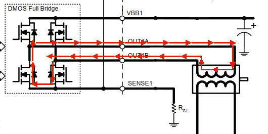
No more external current flows in this phase, the voltage drop at the shunt is 0. Energy is now only drawn from the coil via the losses in its ohmic resistance and possibly (during movement) via the magnetic fields in the motor. The current now only drops more slowly. However, the driver cannot measure this current either, which is why this mode is also terminated in a time-controlled manner and it reverts to step 1
To be continued ... ?