Hello guys! I think my booloader is corrupted because the L led is off but the computer detects it. And I also read from this: http://arduino.cc/en/Guide/troubleshooting
The example are from the blue diecimila while mine is red and the connections are different.
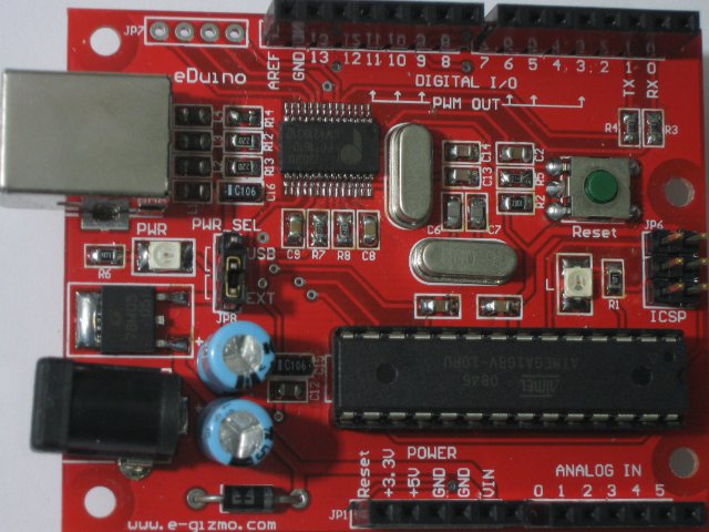
As you can see from the pictures. There are no x3 from the red diecimila, only C8, R9, R7, C9.
And what are those socket wire's called?
CrossRoads:
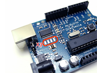
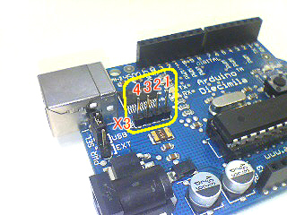
If you look at the FTDI chip in the two pictues, you will see that it is flipped 180 degrees around. So X3 on Diecimila is JP7 on the red board.
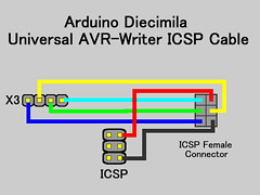
You can see that X3-1 goes to FTDI chip pin 11,
X3-2 goes to pin 9,
X3-3 goes to pin 10, and
X3-4 goes to pin 6
Looking at the red board, and calling the pin nearest the mounting hole JP7-1, it appears:
JP7-1 goes to FTDI chip pin 11,
JP7-2 goes to 10,
JP7-3 goes to 9,
JP7-4 goes to 6,
So not quite a 1-1 match with X3. Need to swap the wires for the middle 2 pins.