yorbus
March 27, 2024, 2:36pm
1
Hello,
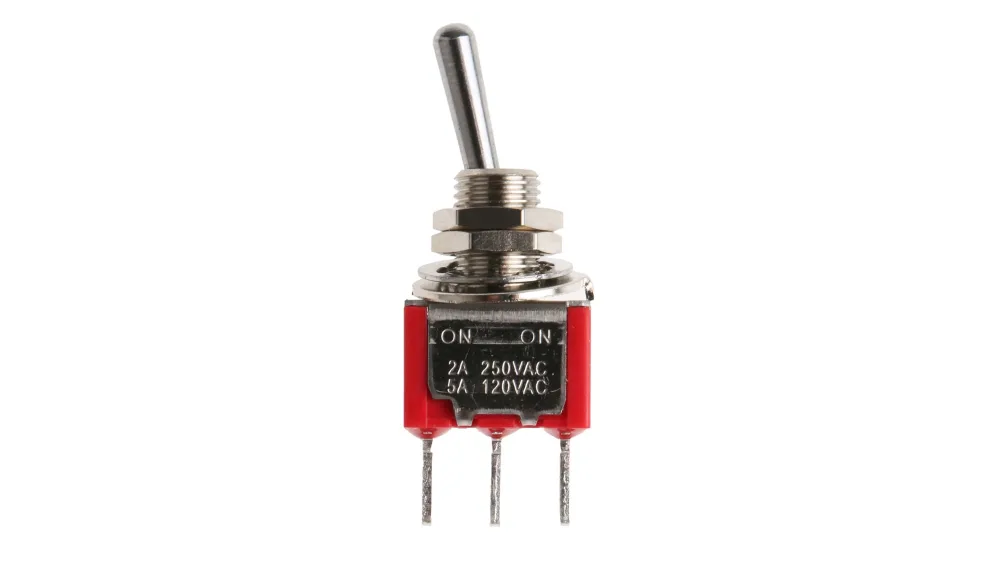
I am in the process of making a remote control. I would like to connect 10 toggle switches (see image)
to my arduino boards so that I have 10 separate digital inputs of 0 or 1. How should I connect these? Is that also with resistors? If so, how?
Thanks in advance!
Greetings Yorbe
Center pin to GND, one of the other pins to an Arduino pin. Use the built-in pull-up resistor.
yorbus
March 27, 2024, 2:41pm
3
Yes, but you have to use also the VCC right?
Example code:
#define SWITCHON LOW

const uint8_t switchPins[] = {2, 3, 4, 5, 6, 7, 8, 9, A0, A1};

void setup()
{
  Serial.begin(115200);
  for (uint8_t cnt = 0; cnt < sizeof(switchPins) / sizeof(switchPins[0]); cnt++)
  {
    pinMode(switchPins[cnt], INPUT_PULLUP);
  }
}

void loop()
{
  for (uint8_t cnt = 0; cnt < sizeof(switchPins) / sizeof(switchPins[0]); cnt++)
  {
    uint8_t pinStatus = digitalRead(switchPins[cnt]);

    Serial.print(F("Switch "));
    Serial.print(cnt);
    if (pinStatus == SWITCHON)
    {
      Serial.println(F(" is on"));
    }
    else
    {
      Serial.println(F(" is off"));
    }
  }
  delay(1000);
}
The code starts with a macro to make your code a little more readable. LOW and HIGH just mean that, SWITCHON makes it clear that LOW means that the switch is on.
The two for-loops use a calculation (sizeof(switchPins) / sizeof(switchPins[0]) to calculate the number of pins and iterate through the pins.
dougp
March 27, 2024, 3:14pm
6
It's there but it's connected through a resistor internal to the processor. See S3 in the diagram below.
1 Like
@LarryD , is the image posted by @dougp yours? I would like to give credit if I use it.
It is VCC when you set pin mode to INPUT_PULLUP
pinMode( pin, INPUT_PULLUP );
that pin sources VCC through 20K to 50K resistance. It is very weak but it is VCC that you can safely ground. The pin reads LOW when grounded.
system
September 23, 2024, 4:03pm
11
This topic was automatically closed 180 days after the last reply. New replies are no longer allowed.