VicenteChazard:
I turned my sights to the ULN2803.Apparently it will works for what I want.
But to make sure I understand properly it's usage:
I supply it with 12V (pin 10), and grounded on pin 9 (joined to GND or the arduino).
Then if I set the inputs pins 1 to 8 HIGH (5v from arduino), the output pins 11 to 18 will be grounded (LOW), or in revers, inputs LOW then outputs will be HIGH.... am I getting this right?
No, that is not right. That would place 12V on the I/O connected to the Arduino, and it would not work for the same reason the 4050 didn't work - mismatched logic levels. You supply 5V to the ULN2803, so the inputs are 5V compatible.
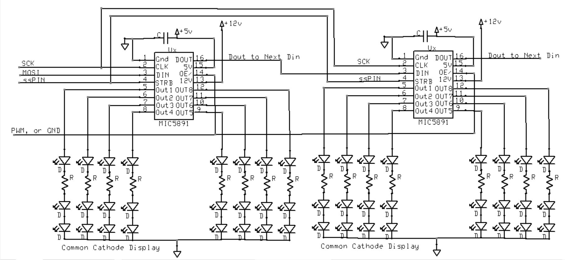
If you have Common Cathode digits, then you need to Source current into them.
MIC5891 works well for that as it is a Sourc Driver + Shift Register in one device.
This is how you would connect them up.
Ok, so with a MIC5891, using only 3 pins from the arduino, I can control up to 8 outputs with 1 chip, or 16 outputs with 2 chips.
If I understand your schematic (I suck at this), 5v to pin 15, 12v to pin 13, all parts with common ground (Arduino, MIC5891 (pin1), and 7-segments displays).
Yes, you have it right.
Yes, you can connect many in series.
Biggest thing to watch for is neat wiring on the clock, data, and the latch pin.
Don't leave off the 0.1uF cap on the 5V pin of each device.
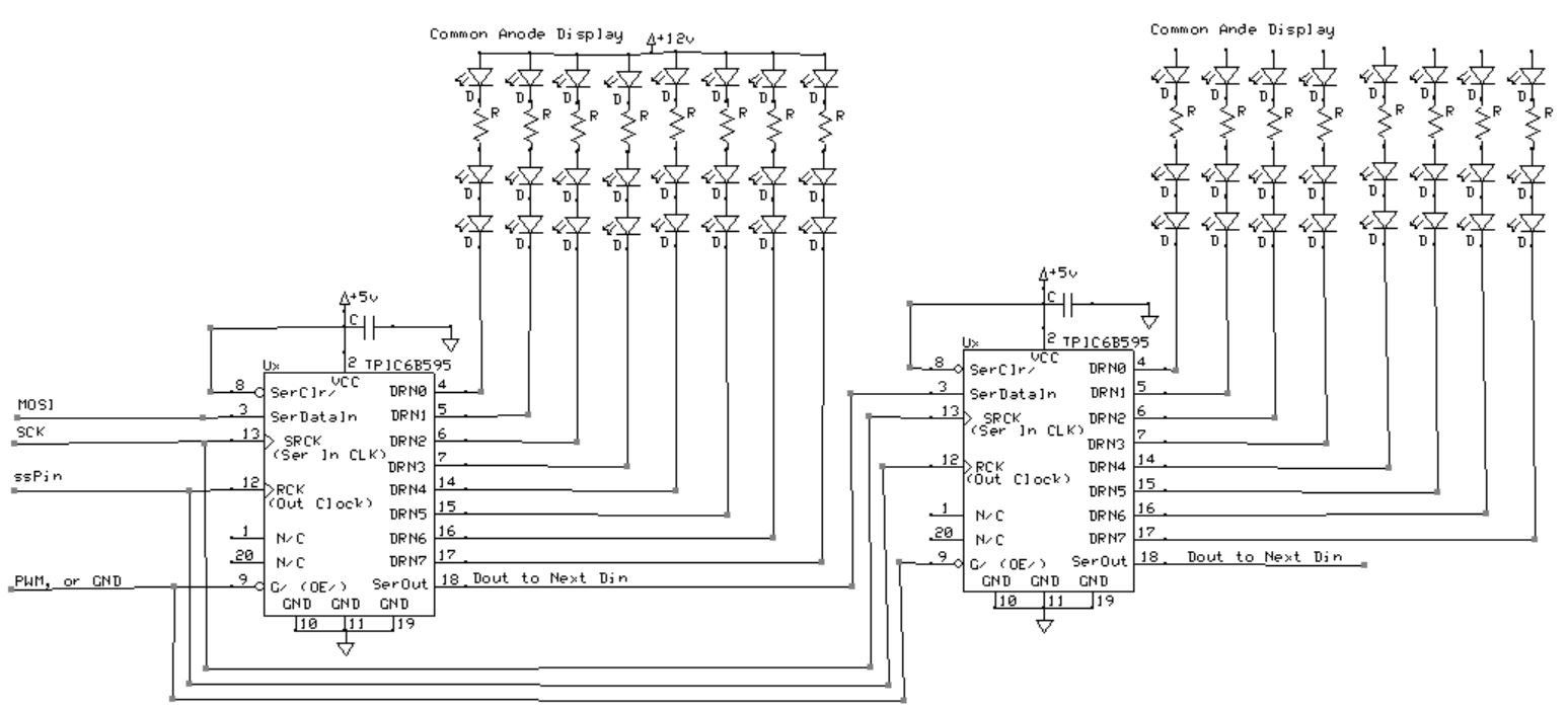
The board I pictured earlier had 12 TPIC6B595, I wanted it to support up to 12 digits and fit in 10cmx10cm board to keep PCB costs down. I'm working on a 12x MCI5891 right now.
I didn't draw out the common SCK, ssPin, or PWM pin, it doesn't add anything to the schematic info for me.
See Reply #15.
Like 74HC595, but you pulse latch High to move the shifter-in data the to the output register,
while '595 needs a rising edge in to clock the data in.