How to connect IMU 9250

Hi everybody,
I've got some trouble with an IMU 9250 10 DOF.
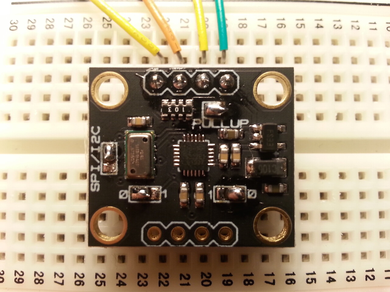
I've done 4 welds, visible in the attachments:

  1. SPI/I2C
  2. PULL UP
  3. Address MPU9250 (set to 0)
  4. Address MS5611 (set to 0)

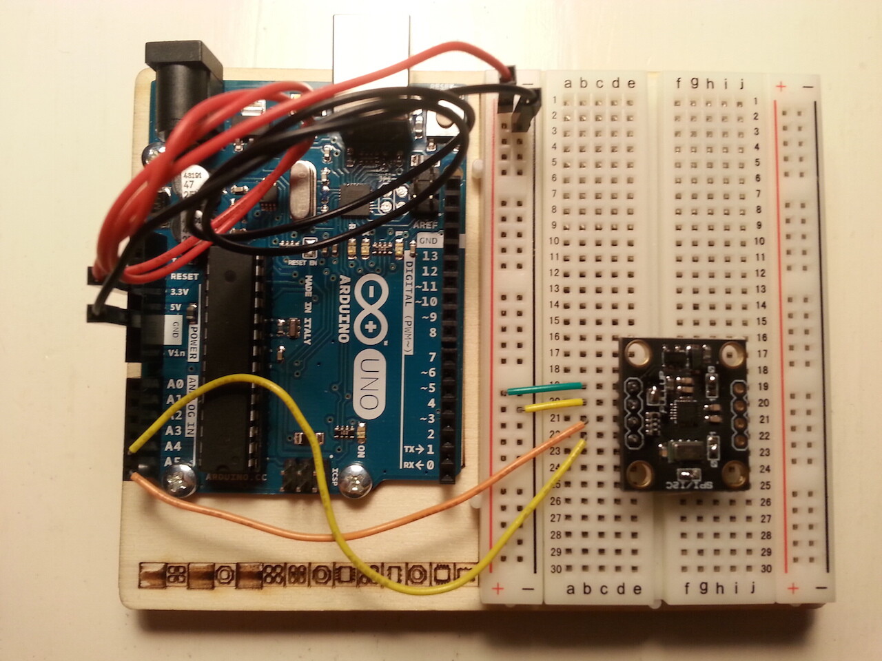
Then I linked the sensor at my Arduino Uno (3.3 V).
I used two I2C Scanner

The first is this one:

// --------------------------------------
// i2c_scanner
//
// Version 1
//    This program (or code that looks like it)
//    can be found in many places.
//    For example on the Arduino.cc forum.
//    The original author is not know.
// Version 2, Juni 2012, Using Arduino 1.0.1
//     Adapted to be as simple as possible by Arduino.cc user Krodal
// Version 3, Feb 26  2013
//    V3 by louarnold
// Version 4, March 3, 2013, Using Arduino 1.0.3
//    by Arduino.cc user Krodal.
//    Changes by louarnold removed.
//    Scanning addresses changed from 0...127 to 1...119,
//    according to the i2c scanner by Nick Gammon
//    http://www.gammon.com.au/forum/?id=10896
// Version 5, March 28, 2013
//    As version 4, but address scans now to 127.
//    A sensor seems to use address 120.
//
//
// This sketch tests the standard 7-bit addresses
// Devices with higher bit address might not be seen properly.
//
 
#include <Wire.h>
 
 
void setup()
{
  Wire.begin();
 
  Serial.begin(9600);
  Serial.println("\nI2C Scanner");
}
 
 
void loop()
{
  byte error, address;
  int nDevices;
 
  Serial.println("Scanning...");
 
  nDevices = 0;
  for(address = 1; address < 127; address++ )
  {
    // The i2c_scanner uses the return value of
    // the Write.endTransmisstion to see if
    // a device did acknowledge to the address.
    Wire.beginTransmission(address);
    error = Wire.endTransmission();
 
    if (error == 0)
    {
      Serial.print("I2C device found at address 0x");
      if (address<16)
        Serial.print("0");
      Serial.print(address,HEX);
      Serial.println("  !");
 
      nDevices++;
    }
    else if (error==4)
    {
      Serial.print("Unknow error at address 0x");
      if (address<16)
        Serial.print("0");
      Serial.println(address,HEX);
    }    
  }
  if (nDevices == 0)
    Serial.println("No I2C devices found\n");
  else
    Serial.println("done\n");
 
  delay(5000);           // wait 5 seconds for next scan
}

and the result is visible in the Attachment "Risultato 1"

The second is this one:

/**
 * I2CScanner.ino -- I2C bus scanner for Arduino
 *
 * 2009,2014, Tod E. Kurt, http://todbot.com/blog/
 *
 */

#include "Wire.h"
extern "C" { 
#include "utility/twi.h"  // from Wire library, so we can do bus scanning
}

// Scan the I2C bus between addresses from_addr and to_addr.
// On each address, call the callback function with the address and result.
// If result==0, address was found, otherwise, address wasn't found
// (can use result to potentially get other status on the I2C bus, see twi.c)
// Assumes Wire.begin() has already been called
void scanI2CBus(byte from_addr, byte to_addr, 
                void(*callback)(byte address, byte result) ) 
{
  byte rc;
  byte data = 0; // not used, just an address to feed to twi_writeTo()
  for( byte addr = from_addr; addr <= to_addr; addr++ ) {
    rc = twi_writeTo(addr, &data, 0, 1, 0);
    callback( addr, rc );
  }
}

// Called when address is found in scanI2CBus()
// Feel free to change this as needed
// (like adding I2C comm code to figure out what kind of I2C device is there)
void scanFunc( byte addr, byte result ) {
  Serial.print("addr: ");
  Serial.print(addr,DEC);
  Serial.print( (result==0) ? " found!":"       ");
  Serial.print( (addr%4) ? "\t":"\n");
}


byte start_address = 1;
byte end_address = 100;

// standard Arduino setup()
void setup()
{
    Wire.begin();

    Serial.begin(19200);
    Serial.println("\nI2CScanner ready!");

    Serial.print("starting scanning of I2C bus from ");
    Serial.print(start_address,DEC);
    Serial.print(" to ");
    Serial.print(end_address,DEC);
    Serial.println("...");

    // start the scan, will call "scanFunc()" on result from each address
    scanI2CBus( start_address, end_address, scanFunc );

    Serial.println("\ndone");
}

// standard Arduino loop()
void loop() 
{
    // Nothing to do here, so we'll just blink the built-in LED
    digitalWrite(13,HIGH);
    delay(300);
    digitalWrite(13,LOW);
    delay(300);
}

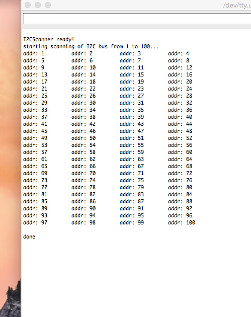
and the result is the attachment "Risultato 2"

If I use the MPU9250_raw.ino (the sketch below), I'll obtain only zeros.
There's another strange thing, i.e. I must to write #include <SPI.h> or I can't uploading my sketch.

#include <SPI.h>


// I2C device class (I2Cdev) demonstration Arduino sketch for MPU9250
// 1/4/2013 original by Conor Forde <me@conorforde.com> at https://github.com/Snowda/MPU9250
//
// Changelog:
//     2014-03-27 - initial release

/* ============================================
I2Cdev device library code is placed under the MIT license

Permission is hereby granted, free of charge, to any person obtaining a copy
of this software and associated documentation files (the "Software"), to deal
in the Software without restriction, including without limitation the rights
to use, copy, modify, merge, publish, distribute, sublicense, and/or sell
copies of the Software, and to permit persons to whom the Software is
furnished to do so, subject to the following conditions:

The above copyright notice and this permission notice shall be included in
all copies or substantial portions of the Software.

THE SOFTWARE IS PROVIDED "AS IS", WITHOUT WARRANTY OF ANY KIND, EXPRESS OR
IMPLIED, INCLUDING BUT NOT LIMITED TO THE WARRANTIES OF MERCHANTABILITY,
FITNESS FOR A PARTICULAR PURPOSE AND NONINFRINGEMENT. IN NO EVENT SHALL THE
AUTHORS OR COPYRIGHT HOLDERS BE LIABLE FOR ANY CLAIM, DAMAGES OR OTHER
LIABILITY, WHETHER IN AN ACTION OF CONTRACT, TORT OR OTHERWISE, ARISING FROM,
OUT OF OR IN CONNECTION WITH THE SOFTWARE OR THE USE OR OTHER DEALINGS IN
THE SOFTWARE.
===============================================
*/

// Arduino Wire library is required if I2Cdev I2CDEV_ARDUINO_WIRE implementation
// is used in I2Cdev.h
#include "Wire.h"

// I2Cdev and MPU9150 must be installed as libraries, or else the .cpp/.h files
// for both classes must be in the include path of your project
#include "I2Cdev.h"
#include "MPU9250.h"

// class default I2C address is 0x68
// specific I2C addresses may be passed as a parameter here
// AD0 low = 0x68 (default for InvenSense evaluation board)
// AD0 high = 0x69
MPU9250 accelgyro;

int16_t ax, ay, az;
int16_t gx, gy, gz;
int16_t mx, my, mz;

#define LED_PIN 13
bool blinkState = false;

void setup() {
    // join I2C bus (I2Cdev library doesn't do this automatically)
    Wire.begin();

    // initialize serial communication
    // (38400 chosen because it works as well at 8MHz as it does at 16MHz, but
    // it's really up to you depending on your project)
    Serial.begin(19200);

    // initialize device
    Serial.println("Initializing I2C devices...");
    accelgyro.initialize();

    // verify connection
    Serial.println("Testing device connections...");
    Serial.println(accelgyro.testConnection() ? "MPU9250 connection successful" : "MPU9250 connection failed");

    // configure Arduino LED for
    pinMode(LED_PIN, OUTPUT);
}

void loop() {
    // read raw accel/gyro measurements from device
    accelgyro.getMotion9(&ax, &ay, &az, &gx, &gy, &gz, &mx, &my, &mz);

    // these methods (and a few others) are also available
    //accelgyro.getAcceleration(&ax, &ay, &az);
    //accelgyro.getRotation(&gx, &gy, &gz);

    // display tab-separated accel/gyro x/y/z values
    Serial.print("a/g/m:\t");
    Serial.print(ax); Serial.print("\t");
    Serial.print(ay); Serial.print("\t");
    Serial.print(az); Serial.print("\t");
    Serial.print(gx); Serial.print("\t");
    Serial.print(gy); Serial.print("\t");
    Serial.print(gz); Serial.print("\t");
    Serial.print(mx); Serial.print("\t");
    Serial.print(my); Serial.print("\t");
    Serial.println(mz);

    // blink LED to indicate activity
    blinkState = !blinkState;
    digitalWrite(LED_PIN, blinkState);
}

What is wrong?
(I apologize for my english)

Risultato 1.png

Is it a Drotek module ? http://www.drotek.fr/shop/en/home/466-imu-10dof-mpu9250-ms5611.html

The first I2C scanner finds 0x68 (MPU-9250) and 0x77 (MS5611).
The second I2C seems to be outdated, perhaps the Wire library has changed since.

The module has a voltage regulator, and selectable 10k pullup resistors.
You selected I2C and pullup resistors enabled ? That is okay.

Please use the Arduino 5V pin to the module VDD. The 3.3V going through the voltage regulator on the module might result into 3.2V for the sensor and pullup resistors. With 5V to VDD, the module runs at 3.3V instead of 3.2V.

Which MPU-9250 library do you use ? This one ? GitHub - Snowda/MPU9250: MPU9250 Accelerometer Driver for Arduino

Yes, it is, a Drotek IMU9250 module.

I changed the I2C library and now I use the jrowberg's one and I obtained with the second I2C scanner a add 12: found! (is it possible only one address?).

The MPU-9250 library is the Snowda's one.

With the MPU9250_raw sketch I obtain only zeros but if I use the MPU9150_raw sketch I'll obtain values different from zero (but the first raw is "MPU9150 connection failed").
All the images are in the attachments.

Thank you for the answer

Did you connect the Arduino 5V to the module VDD ?

I think that if the connection failed, then it's no use looking at the values.
Please don't use the second i2c scanner. It should do the same thing, but perhaps it is outdated.

Let this i2c_scanner run for a while to see if it is stable : Arduino Playground - I2cScanner
Run this Multi Speed I2C Scanner to test your I2C more : MultiSpeed I2C Scanner - 50,100,200,400 KHz. - Libraries - Arduino Forum
There is a link on that page to GitHub for the latest code : Arduino/sketches/MultiSpeedI2CScanner at master · RobTillaart/Arduino · GitHub

I don't have a MPU-9250 myself, so I can't test the libraries.

If the Snowda library reports that the connection failed, then the testConnection() failed, which does only read the WHO_AM_I register.
The WHO_AM_I is not straightforward. There are two valid numbers for it : WHOAMI_RESET_VAL (0x71) and WHOAMI_DEFAULT_VAL (0x68).
Perhaps there is something wrong with the initialize() function, or a timing problem.

Yes, I did.
The IMU is connected to the V5.

I'm trying the FreeIMU library but I've got the same problems.
I' ve noticed if I'm using the I2Cdev library in the Varesano's files I must to add #include <SPI.h> for uploading the sketch but the result of the MPU6050_raw is always a lot of zeros.
If change the I2Cdev library with the latest I2Cdev I can't uploading the sketch.

The Arduino has changed the way files are include. So adding a #include <SPI.h> is normal.

Why can't you upload the sketch, with the latest I2Cdevlib ? What went wrong ?

I think you can try as many libraries as you want, that doesn't seem to go in the right direction.
You want to get good numbers, but I want to communicate with the sensor first.

Did you let the i2c_scanner run for a while? You can wiggle the wires while it is running, perhaps the breadboard has a bad contact.
Could you move the sensor and wires to other locations on the breadboard ? Such simple things might help a lot.
Did you run the Multi Speed I2C Scanner ? What was the output ?

If both I2C Scanners are working stable, then I would like to read the WHO_AM_I register. You may have to change the library and make a few test sketches for that.

If I use the I2Cdev upgraded I'll find this message.

Arduino:1.6.1 (Mac OS X), Scheda:"Arduino Uno"

^
In file included from /Users/Leo/Documents/Arduino/libraries/MPU60X0/MPU60X0.h:40:0,
                 from /Users/Leo/Documents/Arduino/libraries/MPU60X0/MPU60X0.cpp:37:
/Users/Leo/Documents/Arduino/libraries/I2Cdev/I2Cdev.h:100:23: error:   initializing argument 4 of 'static int8_t I2Cdev::readBytes(uint8_t, uint8_t, uint8_t, uint8_t*, uint16_t)' [-fpermissive]
         static int8_t readBytes(uint8_t devAddr, uint8_t regAddr, uint8_t length, uint8_t *data, uint16_t timeout=I2Cdev::readTimeout);
                       ^
/Users/Leo/Documents/Arduino/libraries/MPU60X0/MPU60X0.cpp:2822:68: error: invalid conversion from 'uint8_t* {aka unsigned char*}' to 'uint16_t {aka unsigned int}' [-fpermissive]
    I2Cdev::readBytes(bSPI, devAddr, MPU60X0_RA_ZA_OFFS_H, 2, buffer);
                                                                    ^
In file included from /Users/Leo/Documents/Arduino/libraries/MPU60X0/MPU60X0.h:40:0,
                 from /Users/Leo/Documents/Arduino/libraries/MPU60X0/MPU60X0.cpp:37:
/Users/Leo/Documents/Arduino/libraries/I2Cdev/I2Cdev.h:100:23: error:   initializing argument 5 of 'static int8_t I2Cdev::readBytes(uint8_t, uint8_t, uint8_t, uint8_t*, uint16_t)' [-fpermissive]
         static int8_t readBytes(uint8_t devAddr, uint8_t regAddr, uint8_t length, uint8_t *data, uint16_t timeout=I2Cdev::readTimeout);

...and other pages and pages of similar things.

The I2C Scanner gives me this result:

ng...
I2C device found at address 0x0C  !
I2C device found at address 0x68  !
I2C device found at address 0x77  !
done

I think the problem is that Varesano call the class MPU60X0 instead of MPU6050 which is used in the I2Cdev library

So now the i2c_scanner detects three devices instead of two, because you have it powered with 5V ? Is that true ?
Perhaps you need a level shifter for the I2C bus.
If the Multi Speed I2C Scanner also finds the same three devices, then I think you can go on without level shifter.

Those error messages indicate that the libraries are not compatible. Perhaps it is a bug. I don't know.
I hope you didn't install too many libraries with the same name.
You can go to Users / Leo / Documents / Arduino / libraries /
and check if those are the libraries that you want.

Could you run the Snowda code, and change the library to print the actual WHO_AM_I that is read from the sensor ?

Peter_n:
Could you run the Snowda code, and change the library to print the actual WHO_AM_I that is read from the sensor ?

How can I do it?

The file MPU9260.ccp, find the function getDeviceID(void).
Print the register value:

uint8_t MPU9250::getDeviceID(void) {
  _whoami = readRegister(MPU9250_WHO_AM_I);

  // Added for a test, print the WHO_AM_I
  Serial.print("WHO_AM_I = 0x");
  Serial.println( _whoami, HEX);

return _whoami;
}

Maybe I've understood the problem.

Drotek calls IMU9250 a IMU9150 with the possibility to connect the sensor with the SPI protocol but InvenSense calls IMU9250 a IMU with different sensors.
So the Snowda's library is not the correct library.

Now I tried a new FreeIMU but there are memory's problem so it's impossible to upload the sketch.

That is weird. I read that when a seller doesn't have the MPU-9150 in stock, they ship the MPU-9250.
Try a few other sketches.

This is a very small one : Lulu's blog | Le blog de Lulu
(It connects VDD to 3.3V, but I prefer 5V).

This one tries to support them all:
http://forum.arduino.cc/index.php?topic=242335.0

@leonarduino87:

finally is your MPU-9250 work ?

hello

I've same MPU9250

It is connected with i2c to a nano v3

when start,
it is initialized and MPU9250 connection failed

any idea ?