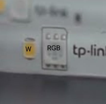
I have a strip of RGBW-IC LEDs, purchased as the TP-Link Tapo L930-5. I cut them down, as my project with Tapo's controller didn't require 5 meters, so I have about 3m worth of LEDs and no controller.
Is there some easy way to determine what control protocol these LEDs use, so I can control the rest of them with an Arduino instead? They are a 12V strip, and this is version 1.8, according to Tapo. This is the original Tapo data sheet, but it doesn't seem to give too many clues as to what chipset they used. Is there a way I can find out?
You can try the various protocols that are supported by any Arduino library for addressable LEDs. The two most used libraries are FastLED and Adafruit Neopixel, so begin with those.
For simplicity, test using a 5V Arduino such as Nano V3 (atmega328). Place a ~500R resistor between the Arduino pin and the Din terminal on the strip. And don't forget to connect the 12V ground to the Arduino ground, of course!
Your link didn't work for me but the datasheet I found said it's controlled by Wi-Fi so that means it's intended for use with their controller and they aren't giving you details for the strip itself...
The straightforward solution is to buy a different, better documented LED strip instead of trying to hack something unknown. Or buy a short one and get the known one working first.
Are the connections marked? There should be +Voltage, ground, and data. If there's also a clock line that's a different protocol whidc may, or may not, work with the library, and of course it needs another connection for the clock.
It's probably compatible with WS2812 / WS2813 ("NeoPixels"). Sometimes they work with 3.3V data but they are intended for 5V data. So use a 5V Arduino and if you only have a 3.3V Arduino use a level shifter. (That's explained in the NeoPixel link.)
And make sure the library runs on your particular Arduino. As you probably know, there are lots of variations and I think these libraries use internal registers & timers that are different in different chips.
From what you can see in the photos on the internet, the strip is made up of groups of 3 RGB LEDs plus 3 white ones and a chip that controls them.
It would be very helpful if you could identify that chip (or attach a photo of it).
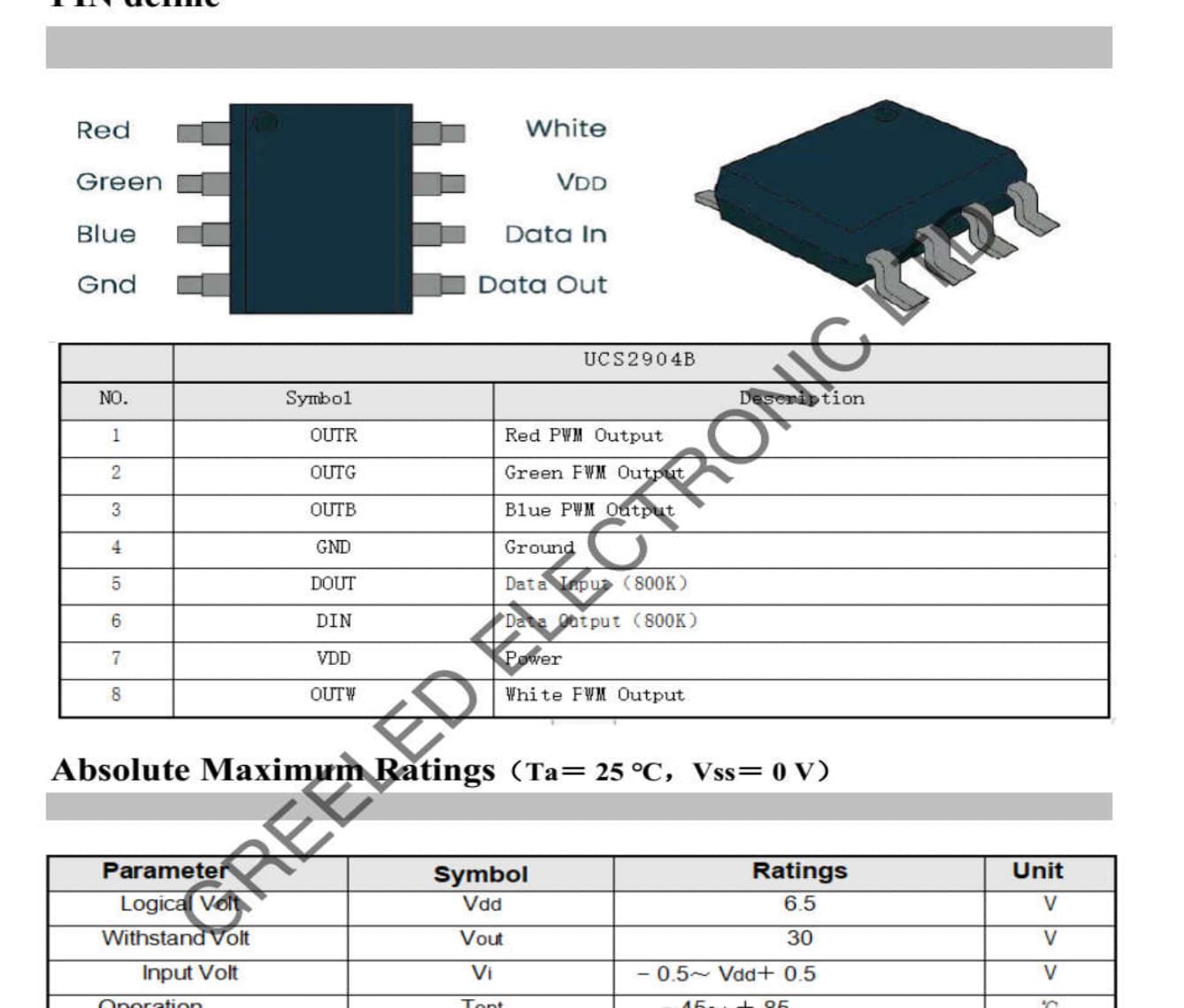
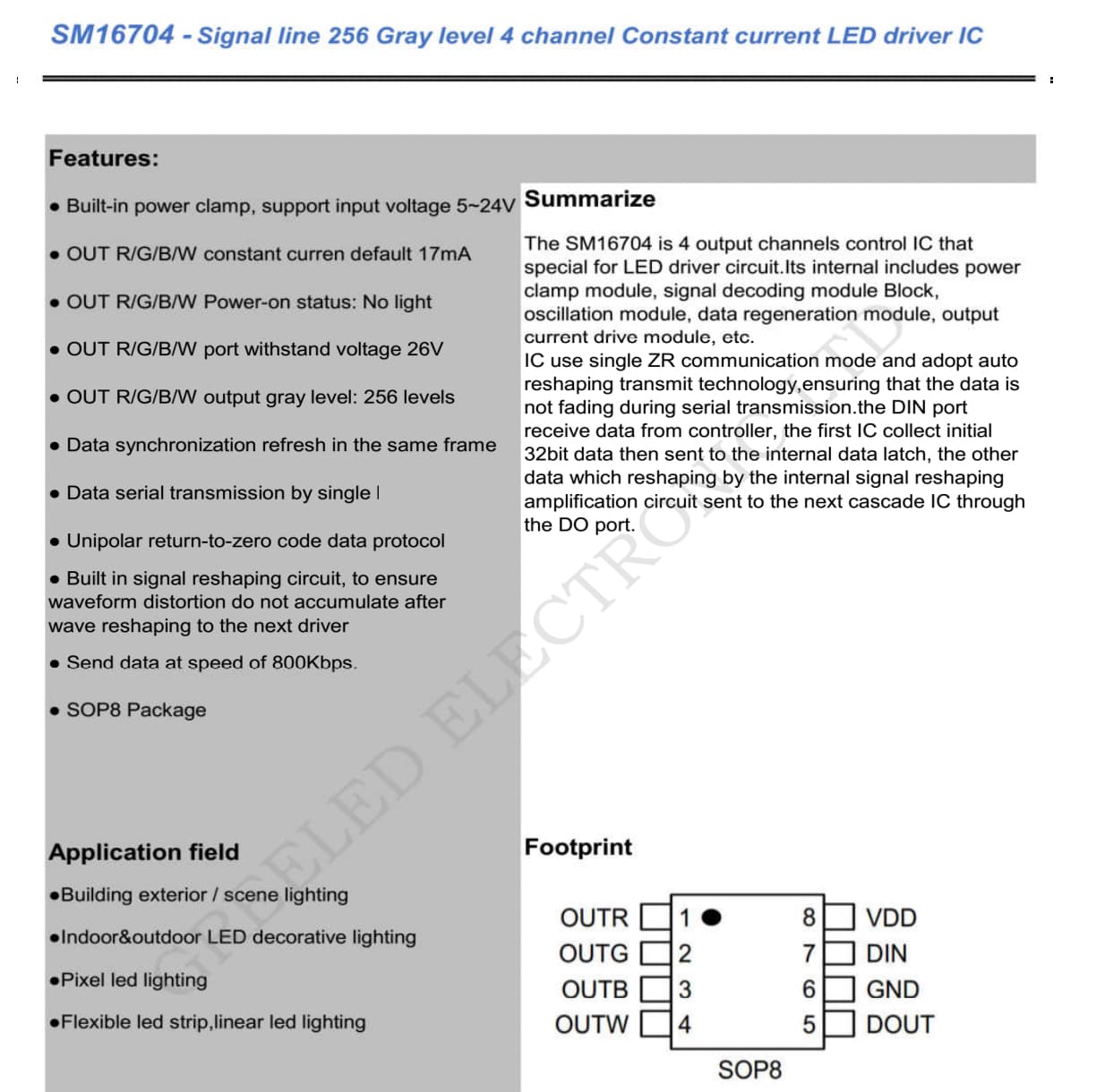
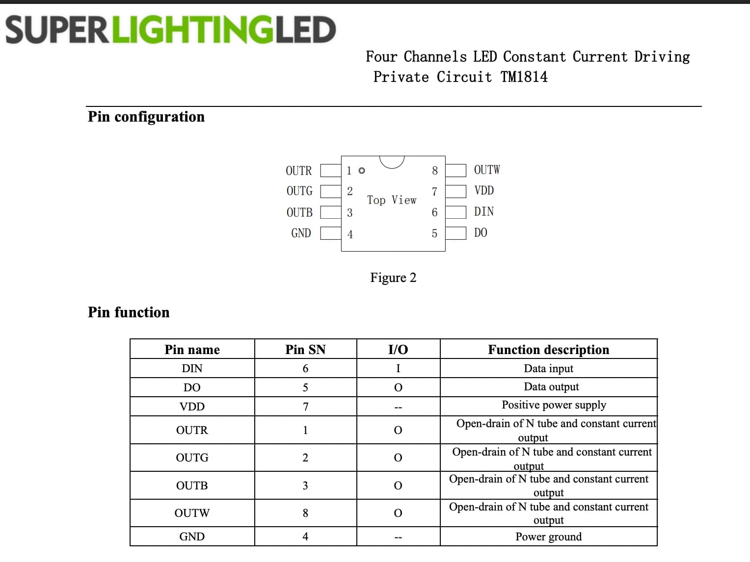
Possible candidates: UCS2904, SM16704 or TM1814.
Thanks, everyone. Obviously I can buy another strip, but I already paid for this one, so might as well put it to use, eh? I've worked with various LED strips and neopixels before, so I'm sure I can get it working once I figure out the protocol.
Trying to answer some questions:
The strip itself has 4 connectors, but when I disassembled the connector plug that came with it (it wouldn't fit in my project), only three of the pins were actually connected.
Top to bottom, they are marked:
+12V
DI or DO (depending on which end)
–
N (this was not connected to the Tapo controller)
I thought at first that the chips were unmarked, but now that I look closer, on a couple of them I can see very, very faint, mostly blurry dark-brown-on-black tiny lettering. Hard for me to make out. If only I had a microscope to put it under
Most of them seem not very sharp of a print, like the ink was smudged, but looks like maaaayyyyybe I can make out WS2811A on one of them. Not sure about that 4th digit, though. It might be 2812? It's blurry and very hard to read. I might have to get that microscope after all.
Good point... With 12V strips, they are usually wired in series in groups of 3, so controlled/addressed in groups of 3.
You may also see one chip for every 3 LEDS and the strip may be marked "cut" or with a scissor icon showing where you can without fouling-up the groups of 3.
Macro setting on camera did not reveal the writing, alas. Looks like I can borrow a video microscope on Wednesday, so perhaps we'll get a more concrete answer then. Cheers!
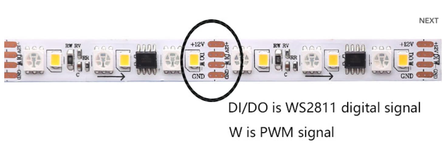
The chips are ws2811, they control the RGB LEDs. Each chip controls a group of 3 RGB LEDs.
The 3rd or 4th pin that's not labelled controls the separate white LEDs. These are not individually controllable but you can switch on/off or dim the white LEDs overall. To control these, you will need to use a MOSFET (maybe IRLZ44) and an Arduino PWM output pin.
My doubt is that you said the 3rd pin was not connected. Are you sure about that?
Thanks. A small correction: I said the 4th pin (labeled N, in the list above) was not connected, and I am very sure. The wire from the Tapo controller was 3-conductor, and there was never any connection to that pad on the strip. I soldered new connectors onto the strip and their controller, using only the 3 pins, and it still works as expected, white LEDs included.
It appears that the white LEDs are not color temperature adjustable — the Tapo app “temperature” settings seem to fake it by adding warm or cool colors from the RGB LEDs. So you may be right in that the white LEDs are merely dimmable, but that 4th pin seems to be unrelated.
Then you have to have a 4 channel controller like:
Or with a 3-channel chip per:
...mayyybe you could do something by interlacing WS2811A chips with integrated WS2812 LEDs, but that would seem overly complicated, expensive, and silly.