You can call it that
Look for another guide.
Having to buy/use a GPS module that does less than what you probably already have is silly.
I assume you can get ESP8266 modules... (see link in page#59).
Leo..
"Extract the time from GPS module only and Display it on 7 segment" these were the words from our great guide ![]()
![]()
![]() Wish i could
Wish i could
per "digit"?
Hello again, need some of your insights. I intend to create my own circuit diagram on proteus for my project : " GPS clock using Arudino ".
Before that, While trying to displaying 0 to 9 on the simulation it isn't running.
This is the code
int DS_pin = 4;
int STCP_pin =3;
int SHCP_pin = 2 ;

int dec_digits   [10] {1,79,18,6,76,36,32,15,0,4};

void setup() {

  pinMode(DS_pin,   OUTPUT);
  pinMode(STCP_pin, OUTPUT);
  pinMode(SHCP_pin, OUTPUT);
}


void   loop() {

for (int i=0;i<10;i++){
  digitalWrite(STCP_pin,LOW);
  shiftOut(DS_pin,   SHCP_pin, LSBFIRST,dec_digits[i]);
  digitalWrite(STCP_pin, HIGH);
  delay(300);

}
An this is the circuit i created. One 7 seg is without ULN2003 driver.Can anyone help me rectify the error? @Etienne_74 @PaulRB @Wawa @kolaha
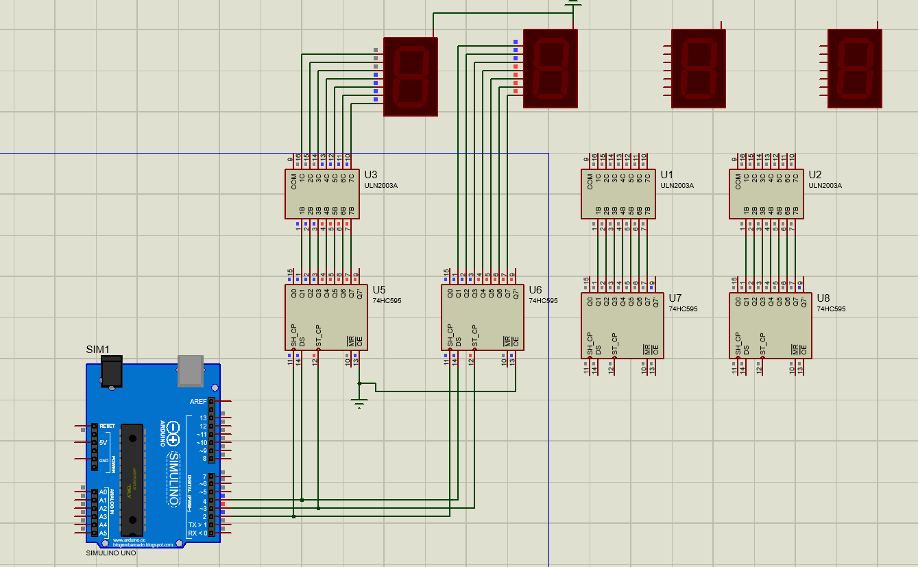
Master Reset on the 4 74HC595 shouldn't be left floating. Tie it to +5V (although Proteus doesn't seen to care !!??)
Do you have voltage parameters inside the LED digit Properties ? Some segments are applied a Logic 1 but seem off
Done
Edited my previous post.
One good solution to spare time with Proteus (and other too) is to start from a close enough design (sample) and modify it to your needs...
Yes I set it to 9V 40mA, As my physical model would be of same config

This is the other sample ciruit which i can refer but it has 4094 shift register and does not contain ULN 2003 driver
This forum adds some context regarding the difference between CH595 and 4094
9V common anode then. You tied the "common pin" to Gnd. This is for Common cathode. Tie it to a (new) 9V rail. But there is a flaw : Logic 1 out of the 74HC595 is 5V and it leaves 4V for the segment to "work" while it should be off. You should have an open collector/drain somewhere... The ULN2003 was also there in that purpose. Any NPN transistor will do (BC847 is a well known one)
Will BC547 work?
Yes, BC547 is the through hole "equivalent"
One thing I didn't notice : your data lines should be cascaded, U5-Q7' driving U6-DS, etc.
The Arduino driving the MSD, D for Digit, allows you to send data LSB first)
It seems you don't understand the need for an ULN (or TPIC) driver and resistors.
The large displays you have use four medium-power LEDs in series, for light-spread and brightness.
That requires a higher voltage than normal size 7-segment displays (about 10volt instead of 2.2volt).
That's why you should use a 12volt power supply, and current limiting resistors.
The extra voltage and CL resistors ensure even current (even brightness) across all segments.
No resistors could result in uneven brightness and/or faster aging of the display.
The ULN is added to the 595 because the 74HC595 can't switch the higher voltage and current.
Same goes for the obsolete CD4094.
Leo..
1 Like

The error earlier was i didnt connect the COM pin of ULN to Common on 7 segment.
Without the ULN the 7 seg is working fine. And it's not the resistors
How should i drive it through ULN ? @Wawa @Etienne_74 @kolaha
i am not sure, but on my modules uln2003 is only 5V connected and acting inverting.
resistor should be on segments, not on anode. otherwise brightness will decrease each additional activated segment.
R7 and R8 should be removed (bypassed) but you need to calculate the value of R1 ... R6 (there should be 7, one is erroneously missing) this way :
from +12V down to ground, there is
- a display segment (its forward voltage under 40mA should be in its datasheet). Lets say 8V (or is it the 9V you told us about)
- a resistor (R1...R7)
- the ULN2003 which is a (set of 7) Darlington transistor (1V)
So 12V = 8V + (R x I) + 1V or R = (12V - 8V - 1V) / .04A = 3V / .04A = 75ohm
As i can see, the current in the segments depends a lot on the on the precision of the 12V power supply. If it provide 13V instead, current rises to (13V - 8V - 1V) / 75 = 53mA.
Actually, the LED forward voltage varies also with current, the increase is not as much but dependent anyway.
The best solution is to have the highest possible power supply voltage (or a current regulation for each segment but it's more complex).
If the current is set to .04A and the acceptable continuous power dissipation in the ½W rated resistors to 0.25W, that's a resistor of P = R x i² => R = P / I² = .25 / .0016 = 150 ohm, ½W.
And PS voltage is now 8V + 150 x .04A + 1V = 15V (16V if your LEDs are 9V instead of 8)
To measure that LEDs forward voltage, try with a multimeter, a 13V car battery (measure it) or anything you can have access to and a 100-150 ohm resistor : yes, (13V - 9V) / .04A = 100 ohm but start with 150 first !
And measure both the voltage across the segment and the current through it. Adjust R to suit your needs and measure the current and voltage again once satisfied (too much current will shorten the LEDs life). Then do the math or report here.
The COM pin does not need to be connected when driving LEDs. It is only needed for inductive loads like relays, motors, solenoids.
Resistors can be on digits. This reduces the component count a little (4 fewer resistors). To avoid the inconsistent brightness problem when different numerals are displayed, a segment-by- segment multiplexing strategy can be used instead of digit-by-digit. However, this reduces the duty cycle of lit segments to 1-in-8 instead of 1-in-4.