I have a power supply module on my breadboard, with jumpers at 5v and 3.3v, but I can't power my ESP8266 with either of these voltages.
trying to put 5v on the VIN pin, it flashes quickly and turns off, putting 3.3V on VIN it does nothing.
I also tried connecting the 3.3V pin directly to the 3V pin on my ESP, but I had the same result, it blinks quickly and turns off.
The only test that worked was directly connecting the 12V DC adapter directly to the VIN pin, but this is not practical at all, since the DC adapter does not connect directly to my breadboard.
I've already checked the voltages on the breadboard and they are stable at 5v and 3.3v
I would like to connect my esp and other components to the 5V or 3.3v lines, how do I do this?
It seems like the issue might be related to the current supply capacity of your power module on the breadboard. The ESP8266, particularly during Wi-Fi transmissions, can draw significant current spikes which your power supply module might not be able to handle. Here are a few steps you can take to resolve this:
Steps to Ensure Proper Power Supply
Check the Current Rating of Your Power Module:
Ensure that the power module on your breadboard can supply sufficient current. The ESP8266 can draw up to 300mA or more during operation, especially when Wi-Fi is active.
Capacitor Across Power Lines:
Add a capacitor across the 3.3V and GND lines close to the ESP8266. A 470µF or higher capacitor can help smooth out any voltage drops caused by current spikes.
Power the ESP8266 Correctly:
If your power module can provide 5V with sufficient current, connect the 5V output to the VIN pin of the ESP8266. This pin is regulated to 3.3V on the board itself.
Ensure that the ground (GND) of the power supply is connected to the ground (GND) of the ESP8266.
Use a Dedicated 3.3V Regulator:
If your power module cannot provide enough current, consider using a separate 3.3V regulator like the AMS1117 which can handle higher currents. Connect the output of the 3.3V regulator to the 3.3V pin of the ESP8266.
Ensure the input of the regulator is connected to a stable 5V or 12V supply.
Practical Connection Steps
Using a 5V Source:
Connect the 5V output of your power module to the VIN pin of the ESP8266.
Connect the ground (GND) of the power module to the ground (GND) of the ESP8266.
Add a 470µF capacitor across the 3.3V and GND pins on the ESP8266.
Using a Separate 3.3V Regulator:
Connect the input of a 3.3V regulator (such as AMS1117) to the 5V output of your power module or directly to your 12V adapter.
Connect the output of the 3.3V regulator to the 3.3V pin of the ESP8266.
Connect the ground (GND) of the 3.3V regulator to the ground (GND) of the ESP8266.
Add a 470µF capacitor between the 3.3V and GND pins on the ESP8266.
Breadboard Power Module
5V ----------------> IN (AMS1117 3.3V Regulator)
GND --------------> GND (AMS1117 3.3V Regulator)

AMS1117 3.3V Regulator
OUT --------------> 3.3V (ESP8266)
GND --------------> GND (ESP8266)
Adding Capacitor:
Place a 470µF capacitor between the 3.3V and GND pins of the ESP8266 to stabilize the power supply.
By ensuring your power supply can provide enough current and stabilizing the voltage with capacitors, your ESP8266 should be able to operate reliably from the 5V or 3.3V lines on your breadboard.
Ensure that the power module on your breadboard can supply sufficient current.
I'm just testing a simple blink, and it doesn't work, the GND is connected correctly
I'm still going to test the use of the Capacitor
I don't have an AMS1117 now
Something is not right.
Should work with 5V.
I don't recomment connecting a capacitor to 3.3V untill you determine what is wrong.
I suspect it may be a breadboard problem.
Have you first loaded the blink sketch?
Yes, via USB blink works,
breadboard works powerd by 3V pin when USB is conected
I suspect it is a power supply module, but I tested 3.3v and 5v lines and they are ok and stable, and the LEDs work by feeding directly on the breadboard with the power supply module.
remembering that the board works by being powered directly by the 12V 2.5A DC adapter(I know it's not really recommended, but it worked)
I have videos of this, but I can't upload them here
Could be the ps module but as I mentioned could also be bad breadboard connections. On the cheap breadboards they can be intermittent. Will conduct on light loads but fail when you draw some current.
Note, I saw that after leaving the ESP connected for a few minutes after it turned off the PS module it became a little hot, not enough to burn my hand but hotter than when it was just turned on
Well you did a few things you were not supposed to so not sure what is wrong
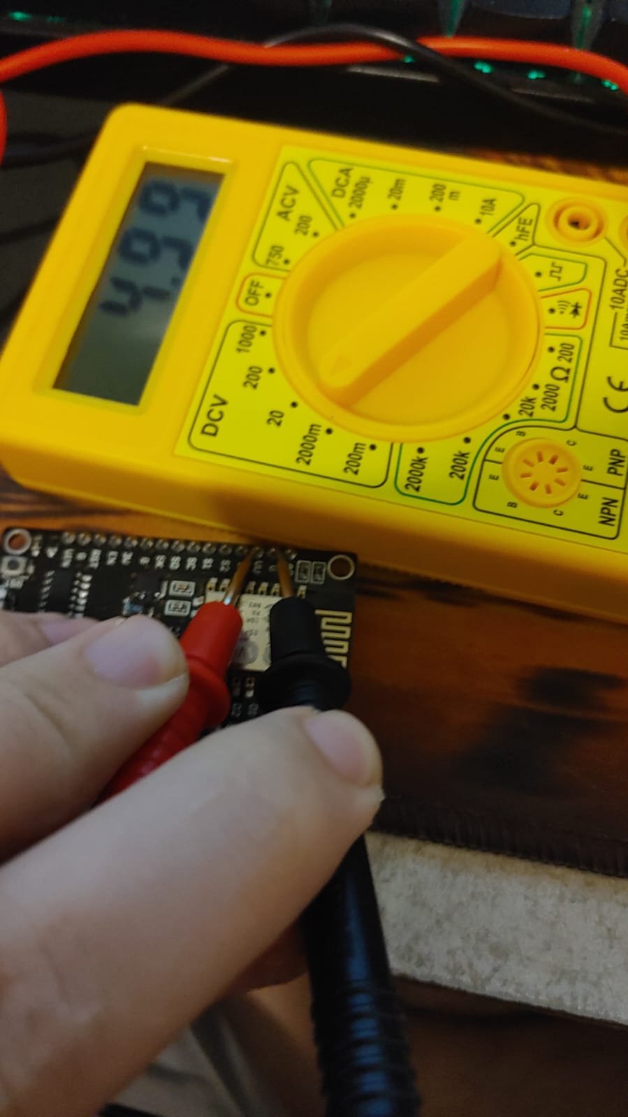
To test the 5V power supply you will need a 20 to 30 ohm 1W resistor.
Connect it between the PS module 5V and ground.
Check the voltage, it should be at least 4.75V. If not, then the PS module is bad.
That looks good.
If it works with USB powert then it should also work with 5V on Vin.
However, I can't explain why it does not.
One more test.
Power the NodeMCU via USB and check the voltage on the Vin pin. It should be greater than 4.75V