Hello @markd833, I just saw this manual but was unable to understand that what inquiry frames do I send for moisture, temp, nitrogen and so on. The manual says

how do we read everything together ?
Hello @markd833, I just saw this manual but was unable to understand that what inquiry frames do I send for moisture, temp, nitrogen and so on. The manual says
how do we read everything together ?
Now you have got your sensor to communicate, I would suggest that you move away from those canned Modbus messages and use a Modbus library instead. It will save you having to manually having to calculate the CRC16 checksum of each message as well as taking care of all the serial comms for you.
Here's a sketch I put together a while back for an NPK sensor where the N, P & K register addresses are in 3 consecutive registers 0x1E, 0x1F and 0x20.
// Attempt to access an NPK sensor to read Nitrogen, Potassium & Phosphorus
// values using an Arduino UNO clone.
//
// This attempt uses the AltSoftSerial & ModbusMaster libraries. Get the libraries
// via the Arduino IDE or manually:
// Get AltSoftSerial at https://github.com/PaulStoffregen/AltSoftSerial
// Get ModbusMaster  at https://github.com/4-20ma/ModbusMaster
//
// RS485 module connected to Arduino UNO as follows:
// RS485 DI signal to pin 9
// RS485 RO signal to pin 8
// RS485 RE signal to pin 7
// RS485 DE signal to pin 6
// RS485 VCC to 5V
// RS485 GND to GND
//
// Assumes that the sensor address is 1, Nitrogen is address 0x1E, Phosphorus is address 0x1F
// and Potassium is address 0x20. Change the code if yours are different.
//
// NOTE: I do not have this sensor, so I simulated it using ModRSsim2 available from https://sourceforge.net/projects/modrssim2/
//

#include <ModbusMaster.h>
#include <AltSoftSerial.h>

#define NITROGEN_ADDR   0x1E
#define PHOSPHORUS_ADDR 0x1F
#define POTASSIUM_ADDR  0x20

#define MAX485_DE      6
#define MAX485_RE_NEG  7

AltSoftSerial swSerial;
ModbusMaster node;

// Put the MAX485 into transmit mode
void preTransmission()
{
  digitalWrite(MAX485_RE_NEG, 1);
  digitalWrite(MAX485_DE, 1);
}

// Put the MAX485 into receive mode
void postTransmission()
{
  digitalWrite(MAX485_RE_NEG, 0);
  digitalWrite(MAX485_DE, 0);
}

void setup() {
  Serial.begin( 9600 );

  // configure the MAX485 RE & DE control signals and enable receive mode
  pinMode(MAX485_RE_NEG, OUTPUT);
  pinMode(MAX485_DE, OUTPUT);
  digitalWrite(MAX485_RE_NEG, 0);
  digitalWrite(MAX485_DE, 0);

  // Modbus communication runs at 9600 baud (change to suit your sensor)
  swSerial.begin(9600);

  // Modbus slave ID of NPK sensor is 1
  node.begin(1, swSerial);

  // Callbacks to allow us to set the RS485 Tx/Rx direction
  node.preTransmission(preTransmission);
  node.postTransmission(postTransmission);
}

void loop() {
  uint8_t result;

  // Request the N, P & K values from the sensor
  // First register is Nitrogen and we want 3 registers
  result = node.readHoldingRegisters(NITROGEN_ADDR, 3);
  if (result == node.ku8MBSuccess)
  {
    Serial.print("   Nitrogen: ");
    Serial.print(node.getResponseBuffer(0x0));
    Serial.println(" mg/kg");

    Serial.print("Phosphorous: ");
    Serial.print(node.getResponseBuffer(0x1));
    Serial.println(" mg/kg");

    Serial.print("  Potassium: ");
    Serial.print(node.getResponseBuffer(0x2));
    Serial.println(" mg/kg");
  } else {
    printModbusError( result );
  }

  Serial.println();
  delay(2000);
}

// print out the error received from the Modbus library
void printModbusError( uint8_t errNum )
{
  switch ( errNum ) {
    case node.ku8MBSuccess:
      Serial.println(F("Success"));
      break;
    case node.ku8MBIllegalFunction:
      Serial.println(F("Illegal Function Exception"));
      break;
    case node.ku8MBIllegalDataAddress:
      Serial.println(F("Illegal Data Address Exception"));
      break;
    case node.ku8MBIllegalDataValue:
      Serial.println(F("Illegal Data Value Exception"));
      break;
    case node.ku8MBSlaveDeviceFailure:
      Serial.println(F("Slave Device Failure"));
      break;
    case node.ku8MBInvalidSlaveID:
      Serial.println(F("Invalid Slave ID"));
      break;
    case node.ku8MBInvalidFunction:
      Serial.println(F("Invalid Function"));
      break;
    case node.ku8MBResponseTimedOut:
      Serial.println(F("Response Timed Out"));
      break;
    case node.ku8MBInvalidCRC:
      Serial.println(F("Invalid CRC"));
      break;
    default:
      Serial.println(F("Unknown Error"));
      break;
  }
}
Obviously, alter the code to suit your own connections. You can use SoftwareSerial instead of AltSoftSerial if you wish.
The querying of the sensor happens in the call to readHoldingRegisters(). The first parameter is the starting register address, and the second parameter is the number of registers to return.
In the case of that table you provided, the starting register address will be 0x00 and you want to read 7 registers.
In order to get the readings, you call getResponseBuffer() with the values 0 to 6 inclusive. Note that these number are not the register addresses, simply the 1st, 2nd or 3rd value returned.
Have you conclusively identified your sensor?
Hello Mark, I have not conclusively identified my sensor that from which company is it but based upon your observation I will input the register values from the manual that you have given me in the code you provided. I will go to my university tomorrow and perform the tests. Will inform you about the update.
Hello @markd833 . I tested the code that you have given and made the required changes
// Attempt to access an NPK sensor to read Nitrogen, Potassium & Phosphorus
// values using an Arduino UNO clone.
//
// This attempt uses the AltSoftSerial & ModbusMaster libraries. Get the libraries
// via the Arduino IDE or manually:
// Get AltSoftSerial at https://github.com/PaulStoffregen/AltSoftSerial
// Get ModbusMaster at https://github.com/4-20ma/ModbusMaster
//
// RS485 module connected to Arduino UNO as follows:
// RS485 DI signal to pin 9
// RS485 RO signal to pin 8
// RS485 RE signal to pin 7
// RS485 DE signal to pin 6
// RS485 VCC to 5V
// RS485 GND to GND
//
// Assumes that the sensor address is 1, Nitrogen is address 0x1E, Phosphorus is address 0x1F
// and Potassium is address 0x20. Change the code if yours are different.
//
// NOTE: I do not have this sensor, so I simulated it using ModRSsim2 available from https://sourceforge.net/projects/modrssim2/
//
#include <ModbusMaster.h>
#include <AltSoftSerial.h>
#define NITROGEN_ADDR 0x00
//#define PHOSPHORUS_ADDR 0x1F
//#define POTASSIUM_ADDR 0x20
#define MAX485_DE 6
#define MAX485_RE_NEG 7
AltSoftSerial swSerial;
ModbusMaster node;
// Put the MAX485 into transmit mode
void preTransmission()
{
digitalWrite(MAX485_RE_NEG, 1);
digitalWrite(MAX485_DE, 1);
}
// Put the MAX485 into receive mode
void postTransmission()
{
digitalWrite(MAX485_RE_NEG, 0);
digitalWrite(MAX485_DE, 0);
}
void setup() {
Serial.begin( 4800 );
// configure the MAX485 RE & DE control signals and enable receive mode
pinMode(MAX485_RE_NEG, OUTPUT);
pinMode(MAX485_DE, OUTPUT);
digitalWrite(MAX485_RE_NEG, 0);
digitalWrite(MAX485_DE, 0);
// Modbus communication runs at 9600 baud (change to suit your sensor)
swSerial.begin(4800);
// Modbus slave ID of NPK sensor is 1
node.begin(1, swSerial);
// Callbacks to allow us to set the RS485 Tx/Rx direction
node.preTransmission(preTransmission);
node.postTransmission(postTransmission);
}
void loop() {
uint8_t result;
// Request the N, P & K values from the sensor
// First register is Nitrogen and we want 3 registers
result = node.readHoldingRegisters(NITROGEN_ADDR, 7);
if (result == node.ku8MBSuccess)
{
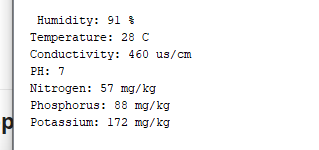
Serial.print(" Humidity: ");
Serial.print(node.getResponseBuffer(0x00));
Serial.println(" mg/kg");
Serial.print(" Temperature: ");
Serial.print(node.getResponseBuffer(0x01));
Serial.println(" mg/kg");
Serial.print(" conductivity: ");
Serial.print(node.getResponseBuffer(0x02));
Serial.println(" mg/kg");
Serial.print(" PH: ");
Serial.print(node.getResponseBuffer(0x03));
Serial.println(" mg/kg");
Serial.print(" Nitrogen: ");
Serial.print(node.getResponseBuffer(0x04));
Serial.println(" mg/kg");
Serial.print(" Potassium: ");
Serial.print(node.getResponseBuffer(0x05));
Serial.println(" mg/kg");
Serial.print(" Phosphorus: ");
Serial.print(node.getResponseBuffer(0x06));
Serial.println(" mg/kg");
Serial.print(" Extra1: ");
Serial.print(node.getResponseBuffer(0x07));
Serial.println(" mg/kg");
Serial.print(" Extra: ");
Serial.print(node.getResponseBuffer(0x08));
Serial.println(" mg/kg");
}
else {
printModbusError( result );
}
Serial.println();
delay(5000);
}
// print out the error received from the Modbus library
void printModbusError( uint8_t errNum )
{
switch ( errNum ) {
case node.ku8MBSuccess:
Serial.println(F("Success"));
break;
case node.ku8MBIllegalFunction:
Serial.println(F("Illegal Function Exception"));
break;
case node.ku8MBIllegalDataAddress:
Serial.println(F("Illegal Data Address Exception"));
break;
case node.ku8MBIllegalDataValue:
Serial.println(F("Illegal Data Value Exception"));
break;
case node.ku8MBSlaveDeviceFailure:
Serial.println(F("Slave Device Failure"));
break;
case node.ku8MBInvalidSlaveID:
Serial.println(F("Invalid Slave ID"));
break;
case node.ku8MBInvalidFunction:
Serial.println(F("Invalid Function"));
break;
case node.ku8MBResponseTimedOut:
Serial.println(F("Response Timed Out"));
break;
case node.ku8MBInvalidCRC:
Serial.println(F("Invalid CRC"));
break;
default:
Serial.println(F("Unknown Error"));
break;
}
}
The changes that I made were:
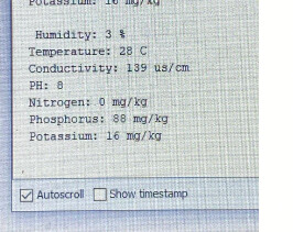
The conclusion that I can draw from results is. This is indeed a 7 in 1 soil moisture sensor. Since it's returning 7 values in the results.
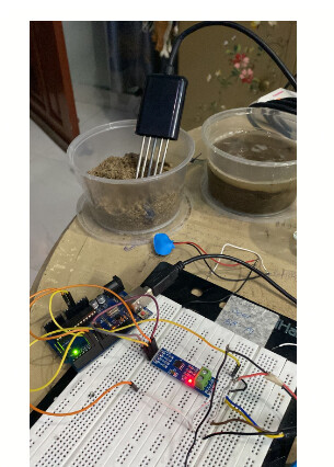
I am attaching the pic for result when soil moisture sensor is inside the soil

This picture result is for when soil moisture sensor is outside the soil (sensor is not touching the soil and is outside)

I can't identify which value is for which parameter. used this convention for naming highlighted in yellow
what I don't understand is

how in PH 56 get's converted to 9
and nitrogen gets converted to 56 from 32
and phosphorus gets converted to 56 to 88
and potassium gets converted to 104 to 104 only how is that working
Sounds like you've made a lot of progress and good news that the sensor is responding reliably.
Ok, so pH: If you receive a value of 5A (hex), then that = 90 (dec). pH is usually sent x10 the actual value so you can get 1 decimal place. Therefore you need to divide the received value by 10 to get the actual value to 1 decimal place. So for a received pH value of 5A (hex) => 90 (dec) => pH 9.0
Same for Nitrogen. You received 20 (hex) => 32 (dec). But, I think N, P & K are the actual values as there are no decimal places so the Nitrogen value is 32 mg/kg.
Same for Phosphorous and Potassium.
Thanks @markd833
The sensors corresponds well. I tested it on 3 soils.
1 Dry soil
partially soluble soil
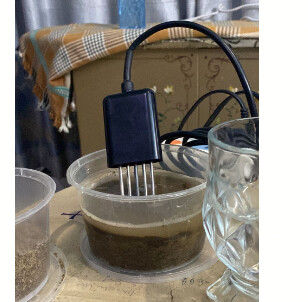

Tap water
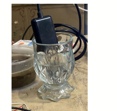
I think responds correctly to the parameters that are there
Now I wanted to ask you one important thing since I need to change the sensor from ArduinoUno to ESP32.
so for that I have
RS485 DI signal to pin 9
RS485 RO signal to pin 8
RS485 RE signal to pin 7
RS485 DE signal to pin 6
which pins should I use for ESP32
and also whether Modbuster and Altsoftserial library be used for ESP32
Connect RE and DE together and use one GPIO to drive them (save one GPIO ![]() ).
).
Im using this modbus master library, with ESP32 and its very good imo.
https://github.com/4-20ma/ModbusMaster
I don't think it would work. When I did this with arduinoUno TX was transmitting and RX was receiving the same message.
It`s not a theory, I have a working device.
With a MAX485 chip, the receive portion of the line driver is enabled when is RE is LOW, and the transmit portion of the line driver is enabled when DE is HIGH. You can set RE LOW and DE HIGH to hear your own transmissions.
As @noobmastha correctly says, using just 1 signal wire connected to both RE & DE, it is not possible to hear your own transmission.
Here's the section of the MAX485 datasheet for your reference.
Thanks @markd833 and @noobmastha. I correctly got it working with ESP32. Didn't used one GPIO for RE & DE instead connected them to 22 and 23.
Thanks again guys highly appreciate your help!
@areebkhan02 I could share your code you made with ESP32 to this email oneyverr@gmail.com I am developing a university project and would be of great help.
Wow! I know Spanish - and I didn't even know - how'd I miss that. ![]()
![]()
![]()
@markd833 Could you help me, I am using a soil ph sensor, I want to communicate it with my esp32 and TTL to rs485 module, but I have this response.
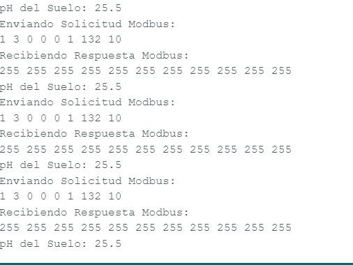
#include <ModbusMaster.h>
#include <Wire.h>

#define RE 25
#define DE 26

const byte ph[] = {0x01, 0x03, 0x00, 0x00, 0x00, 0x01, 0x84, 0x0A};
byte values[11];

void setup() {
  Serial.begin(9600);
  Serial2.begin(4800, SERIAL_8N1, 16, 17); // Usa Serial2 para la comunicación
  pinMode(RE, LOW);
  pinMode(DE,LOW);
}

void loop() {
  byte val;

  // Habilitar transmisor y receptor
  digitalWrite(DE, LOW);
  digitalWrite(RE, LOW);
  delay(10);

  // Enviar solicitud Modbus
  Serial.println("Enviando Solicitud Modbus:");
  for (byte i = 0; i < sizeof(ph); i++) {
    Serial.print(ph[i], DEC);
    Serial.print(" ");
  }
  Serial.println();

  // Verificar si la solicitud Modbus se envía correctamente
  if (Serial2.write(ph, sizeof(ph)) == 8) {
    // Deshabilitar transmisor y receptor
    digitalWrite(DE, LOW);
    digitalWrite(RE, LOW);

    // Recibir e imprimir la respuesta Modbus
    Serial.println("Recibiendo Respuesta Modbus:");
    for (byte i = 0; i < 11; i++) {
      values[i] = Serial2.read();
      Serial.print(values[i], DEC);
      Serial.print(" ");
    }
    Serial.println();
  } else {
    Serial.println("Error: Solicitud Modbus no enviada correctamente");
  }

  // Calcular e imprimir el pH del suelo
  float soil_ph = float(values[4]) / 10;
  Serial.print("pH del Suelo: ");
  Serial.println(soil_ph, 1);

  delay(3000);
}
Your code includes the modbusmaster library but you don't use it.
Have a look at this discussion:
And the code in post #6. It shows how to use the modbusmaster library.
It will need a few simple tweaks for your sensor, but it will handle the modbus timings for you.
Hello dear @markd833 and @areebkhan02. Can you please help? I performed all the steps above up to post #21, but when I reconnected my sensor I had no RX address. Would be this associated with the sensor problem or voltage powered the sensor? Can you please give me a direction, where to start? I am also working with seven in one soil sensor.
Thanks in advance.


