Hello,
I'm not sure if this is the right forum for this question, if not, my apologies in advnce but not sure where to post this otherwise.
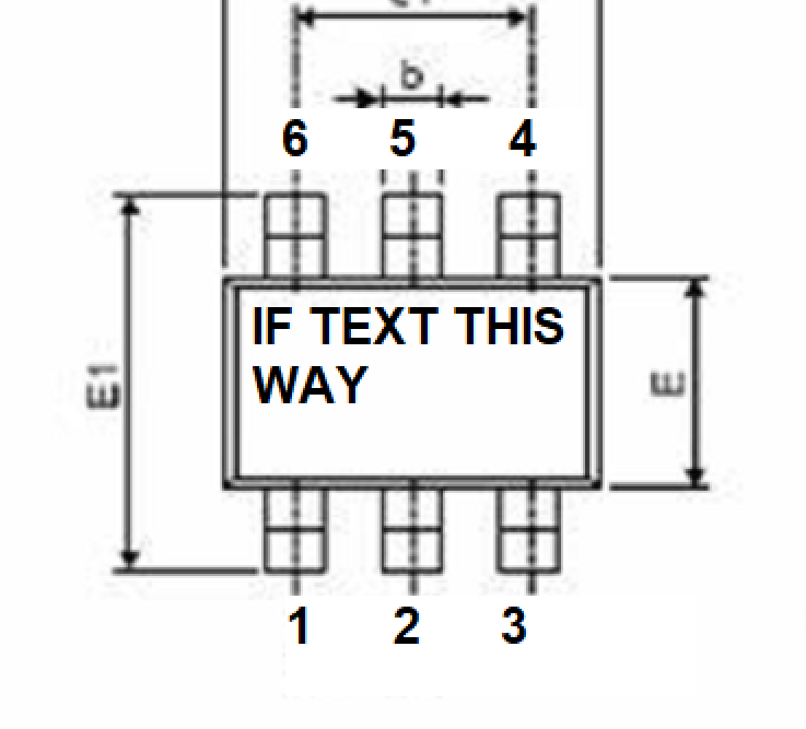
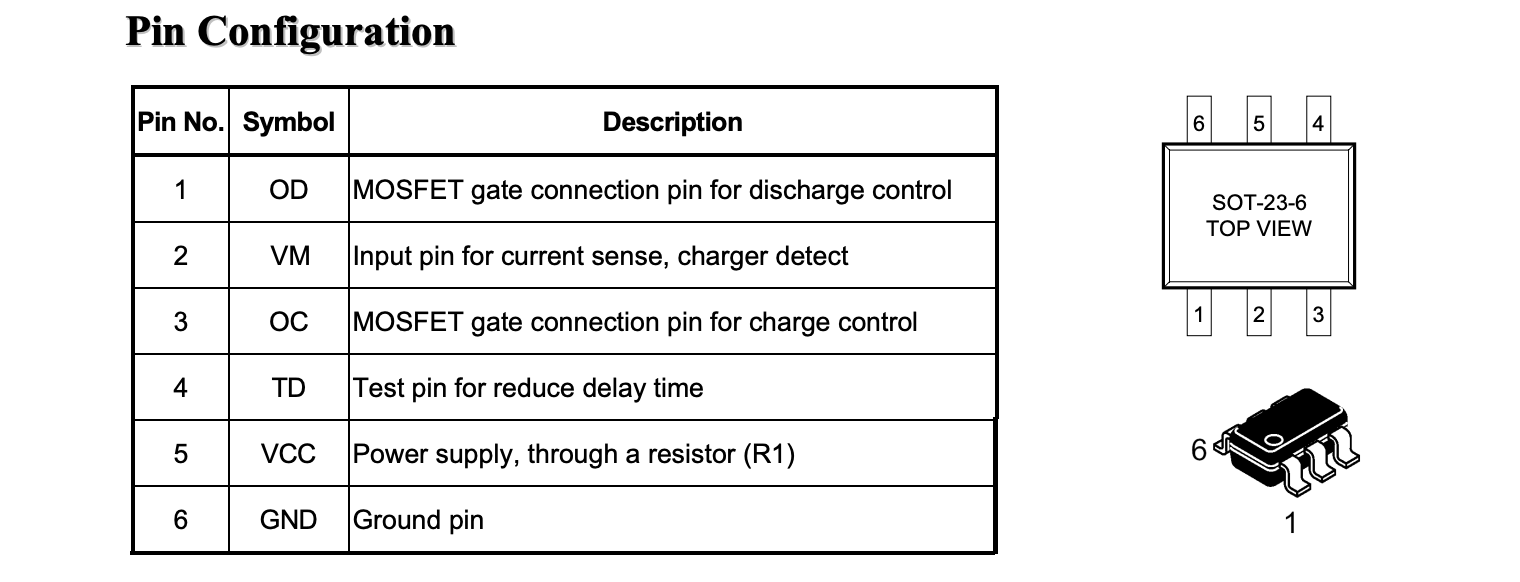
I designed a circuit board in Eagle and just had my part delivered. I am trying to solder FS8205 chip onto the board but there's no indication how the chip should be positioned, no dot or anything. The datasheet shows the pinout as per the picture I am including. I also included the link to the actual datasheet. It is a chip that contains 2 MOSFET, so they share the drain but s1-g1 and s2-g2 will not align if I rotate them by 180 degrees. Any ideas?
Thanks.
https://datasheet.lcsc.com/lcsc/1810110910_Fortune-Semicon-FS8205_C32254.pdf
Hi, @higgenkreuz_007
Should help.
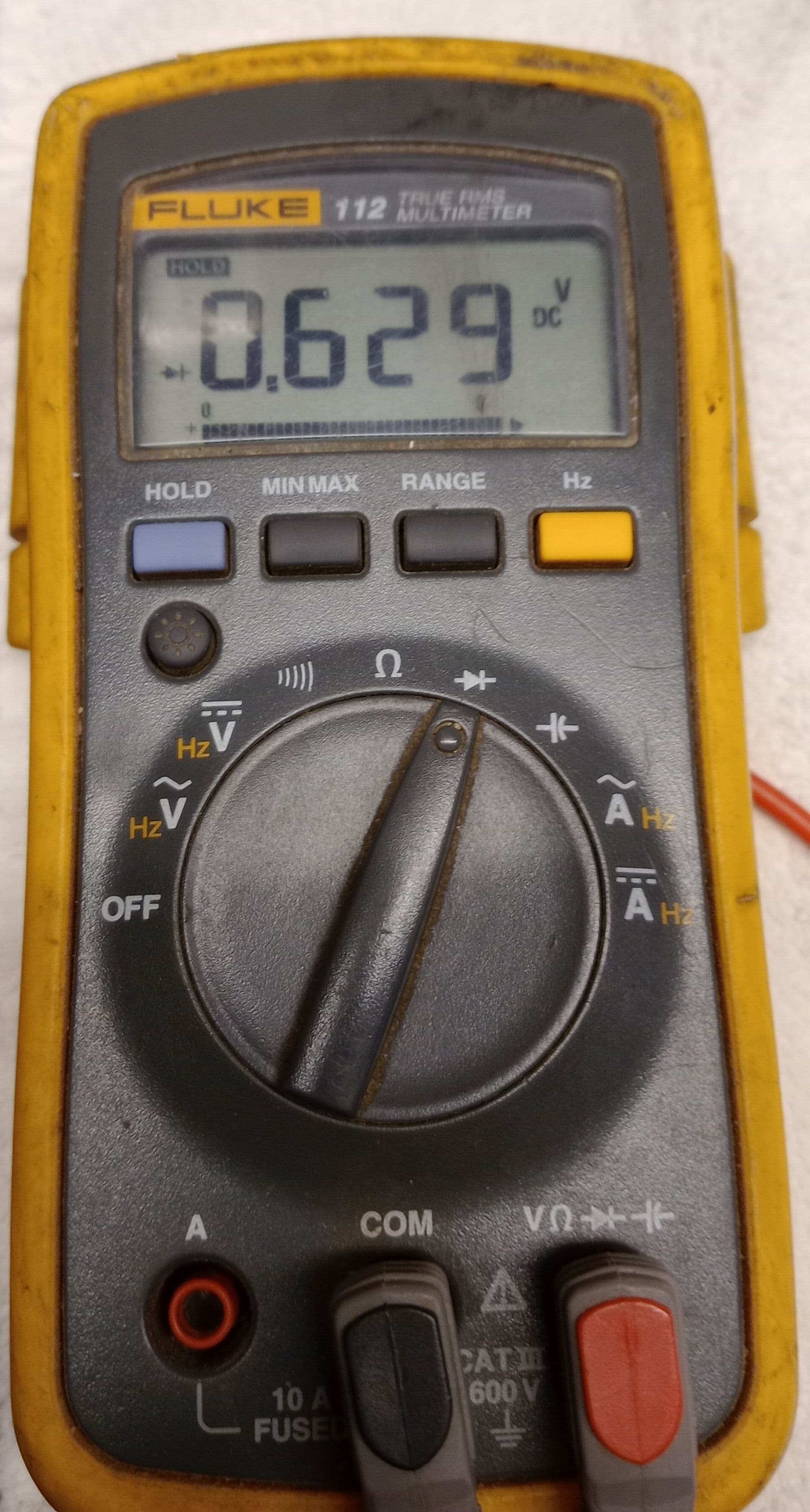
Use DMM in diode mode and check for diodes between S1 and D12 and S2.
Tom.. 


Take a close look at the body of the MosFet. There should be a dot or a depression of a dot in the corner indicating pin 1.
There maybe a 1/2 moon depression on the end between pin 1 and pin 6.

The only thing I can think of is to take a multimeter to measure resistance (or a led with a 1K series resistor) between S1 and D12 to identify where the body diode is. Current will flow through it.
The opposite pins are G2 and D12, so no current will flow through.
[edit] I see @TomGeorge had the same idea already
I have boards and the chip i have soldered it on, but i am not near my workshop for another few weeks, but i just had a look at a fully populated board, and your should mark @TomGeorge post#2 as the solution.
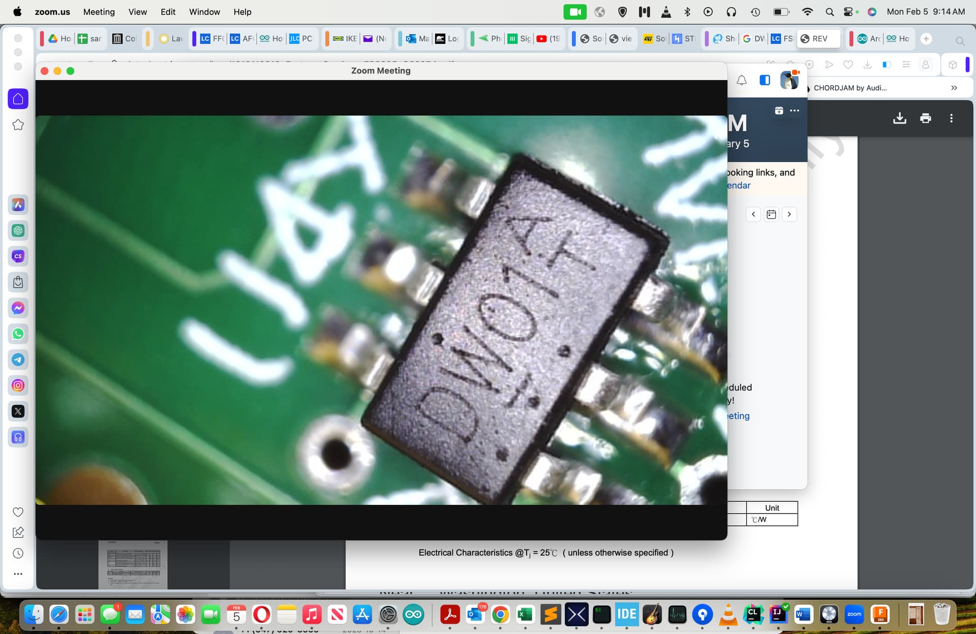
The mosfets i have actually have FS8205 written on there in that exact way.
Hi guys,
I tested it with my DMM, good idea, it looks like the positioning is exactly as per @TomGeorge post#2.
Incidentally, I have another problematic chip, DW01A (I'm building a battery charger). The datasheet is clear on the marking but it seems I have several dots on this thing. When in doubt, can I just orient the chip based on the orientation of the text on the chip? Thank you once again, your input was really helpful.
Yes, it tells the forward voltage drop.