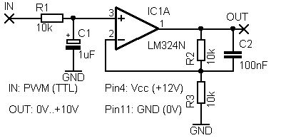
No, I don't have the schematic. I'm also fairly confident that the little pulse doesn't matter and that if the circuit was fed the same voltage, without that tiny, tiny blip, that it wouldn't care. The real question is which of the above circuits would most likely be correct? It will be very annoying, slow, and tedious to source all of the parts just for this tiny little feature. It's super crazy that there isn't already an off-the-shelf PWM-controlled buck converter out there..
So the whole story is about interfacing a hall effect joystick with an Arduino.
This joystick runs on 5volt.
Red = positive, black is negative.
The coloured wires are the axis outputs.
Blue = x, yellow = y, switch = white.
2.5volt when idle.
This joystick can be read with two analogue inputs.
Don't understand why some other voltage is needed.
Leo..
Wawa:
So the whole story is about interfacing a hall effect joystick with an Arduino.This joystick runs on 5volt.
Red = positive, black is negative.The coloured wires are the axis outputs.
Blue = x, yellow = y, switch = white.
2.5volt when idle.This joystick can be read with two analogue inputs.
Don't understand why some other voltage is needed.
Leo..
No, no. It is not about that at all. You have a power chair. You want to control it remotely instead of by joystick. You grab the joystick box (which also contains all of the electronics for the power chair), and you cut out the joystick. Now you want to make the power chair electronics think the joystick is still there but actually you are emulating it with an arduino or some other circuit. This other circuit, or arduino, is fed PWM signals from a RC receiver.
0-10V is a common analog control voltage for industrial equipment. I've bought 5-10V converters to do this from eBay in the past.
David82:
you cut out the joystick. Now you want to make the power chair electronics think the joystick is still there but actually you are emulating it with an arduino or some other circuit.This other circuit, or arduino, is fed PWM signals from a RC receiver.
Here is what my pea-brain thinks:
- That joystick runs on 5volt (datasheet).
If you remove the joystick (that was producing 0-5volt for the circuit), you have to generate 0-5volt with an Arduino.
That is very easy. Just a PWM signal, resistor and a cap.
A 4053 (analogue switch) could be used to switch between joystick and Arduino if needed. - A remote control (RF or IR) could send data (not PWM) to the Arduino to emulate the original joystick.
Leo..
Edit.
Just saw your OTHER lawnmower post (spreading problems is confusing).
This joystick is used on a 12volt supply (6volt center).
You just need an rail2rail opamp that amplifies Arduino's smoothed PWM 2.4 times.
MorganS:
0-10V is a common analog control voltage for industrial equipment. I've bought 5-10V converters to do this from eBay in the past.
Do you have an example link, or a search phrase I can use?
Would this LM358 breakout board work? SparkFun OpAmp Breakout - LMV358 - BOB-09816 - SparkFun Electronics
I could use a circuit that converts PWM from the RC receiver to flat DC voltage, then feed it into this LM358. It would be nice to find a breakeout board that does both, conversion of PWM to DC, and amplification.
The first comment on that LM358 breakout says it won't do DC.
Of the circuits presented above, option B looks the best. Option A is a power supply and option C doesn't specify which opamp to use.

So I built circuit B.
Problems:
Result is a sawtooth wave that varies by .25v, if I cheat and use two 1uF caps in parallel instead of one.
The 100nF cap does nothing.
The reaction time is too slow to be usable for RC control (it will cause the user to constantly over correct)
Is there such a thing as a playing card-sized, PWM controlled, low-amp, programmable, dc power supply? That's what I need...