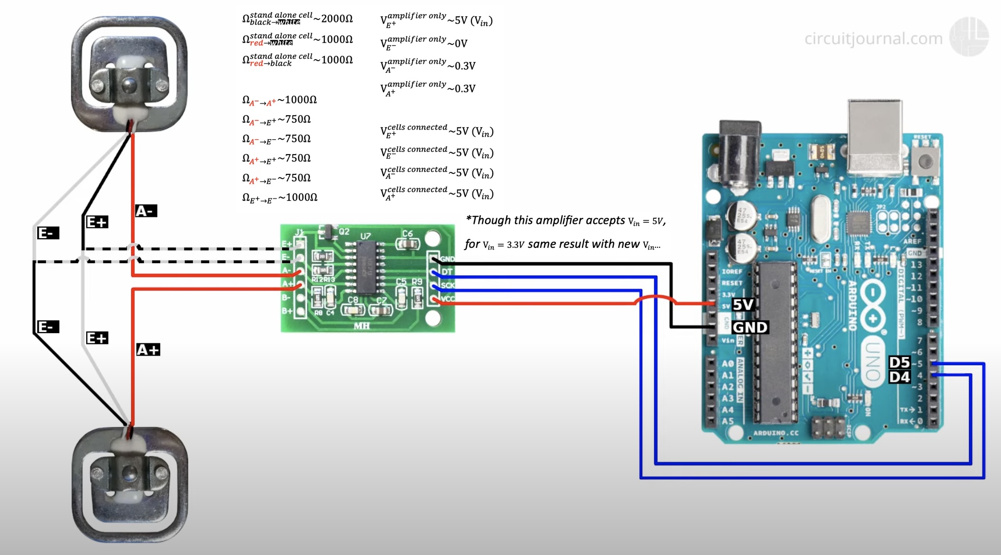
I used the Half bridge configuration - 2 load cells.
The system works, but after tare & calibration, for every weight I get a noisy reading around the known mass value I used for calibration.
Repeated with other ESP32 board, HX711 amplifiers & load cell sensors, but same behavior.
Since I'm SW engineer, I inspected the code & debugged it - looks fine on that front.
So I suspect either:
Faulty HW (even though I repeated with different)
Proposed wiring diagram in the tutorial is wrong
As a SW engineer I don't know how to solder properly etc.
This is the debugging I performed - I would like to know if already from here the issue might be seen + suggestion to other debugging options.
Thanks in advance!
V_E- doesn't look right. I would expect it to be zero so as to apply an 5V excitation voltage across E+/E- junctions between the two load cells. Try checking E+/E- voltage with no load cell attached.
And 300mV across A+/A- is outside the range that the HX711 can accept and amplify linearly.
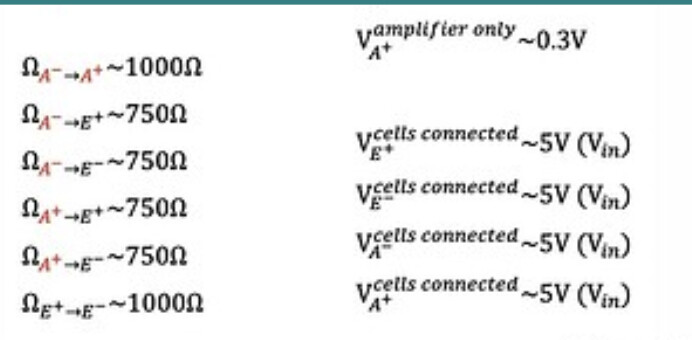
The reported resistances look correct for a properly wired ring made out of 4x 1000 ohm resistances.
That says V_A+. E+/E- should be outputs from the HX711 providing the "Excitation voltage" to the bridge, and A+/A- are inputs back into the amplifier in the HX711.
E+ to E- should be 5V,on the HX711, whether it's attached to the bridge or not. Measuring across A+ to A- with nothing attached would tell you more about your meter than it would tell you about the HX711.
If E+/E- is significantly less than 5V, then something's wrong with the HX711
For example if I calibrate with 200 (the Git repo works unitless, so in that case grams), I get constantly random numbers in the range of [-100,300] no matter what load I apply - that's the issue...
Similarly when I calibrated with 80kg etc.
If your A+/A- input voltage is bigger than 20mv (40mV?) then the amp will peg at one end of it's range about you'll be calibrating between nearly constant raw numbers, making the slope of the calibration be random.
Tha result looks like the wiring of the bridge is shorting the E+ to E-. Sometimes the colors are wrong on the load cells. Disconnect the load cells completely and check that the resistance from black-to-while is 2000 ohms, and from black to red =1000 ohms, and white to-red=1000 ohms on each of them. Red should the middle of the half-bridge. If not, whatever are the middles of the half-bridges should connect to A+/A-.
OK, the only thing I can think of is that the E- on the HX711 board isn't good. If you wire just one load cell's white/black to E+/E-, E+ should be 5V and E- should be zero, with the red wire at 5V*1000/(1000+1000)= 2.5V If E- comes up to 5V, it is a bad E- on the HX711.
When connected and operating, the bridge should be balanced enough to deliver a +/-20mV signal into A+/A-, If it does more, then the +/-20mV times the Gain hits the 0V/5Vrails at +/-0.020*128=+/-2.5V
Since when connected, everything is a 5V, then a 0.0000V difference between A+/A- is delivering a constant raw value to your calibration routine, and you are probably calibrating out-of-spec ADC noise to get your calibration slope
Let me get this correct.
You can successfully make a calibration but when you go back to make an actual measurement with tha same weight you used for the calibration, that is when you get the crazy values.