Note added in 2020, based on this thread. Board 1 also does not have E- grounded, so the on-board voltage regulator does not work properly. That may explain some of the differences with Board 2.
Thought I'd share results of tests I did on two HX711 boards using a barebones Arduino and different power sources. Each test consisted of taking 10,000 samples and then processing the reads as indicated.
Quick summary: looks like this 24 bit ADC will give about 14 to 15 noise-free bits. Maybe 16 if you're careful with grounding and shielding and use a very low noise power supply and sensor.
These tests do not reflect degradation that occurs due to creep, hysteresis, gain errors, etc. except to the extent that any time-related effects (e.g., creep) occurred during sampling (10000 samples at 10 sps takes about 17 minutes).
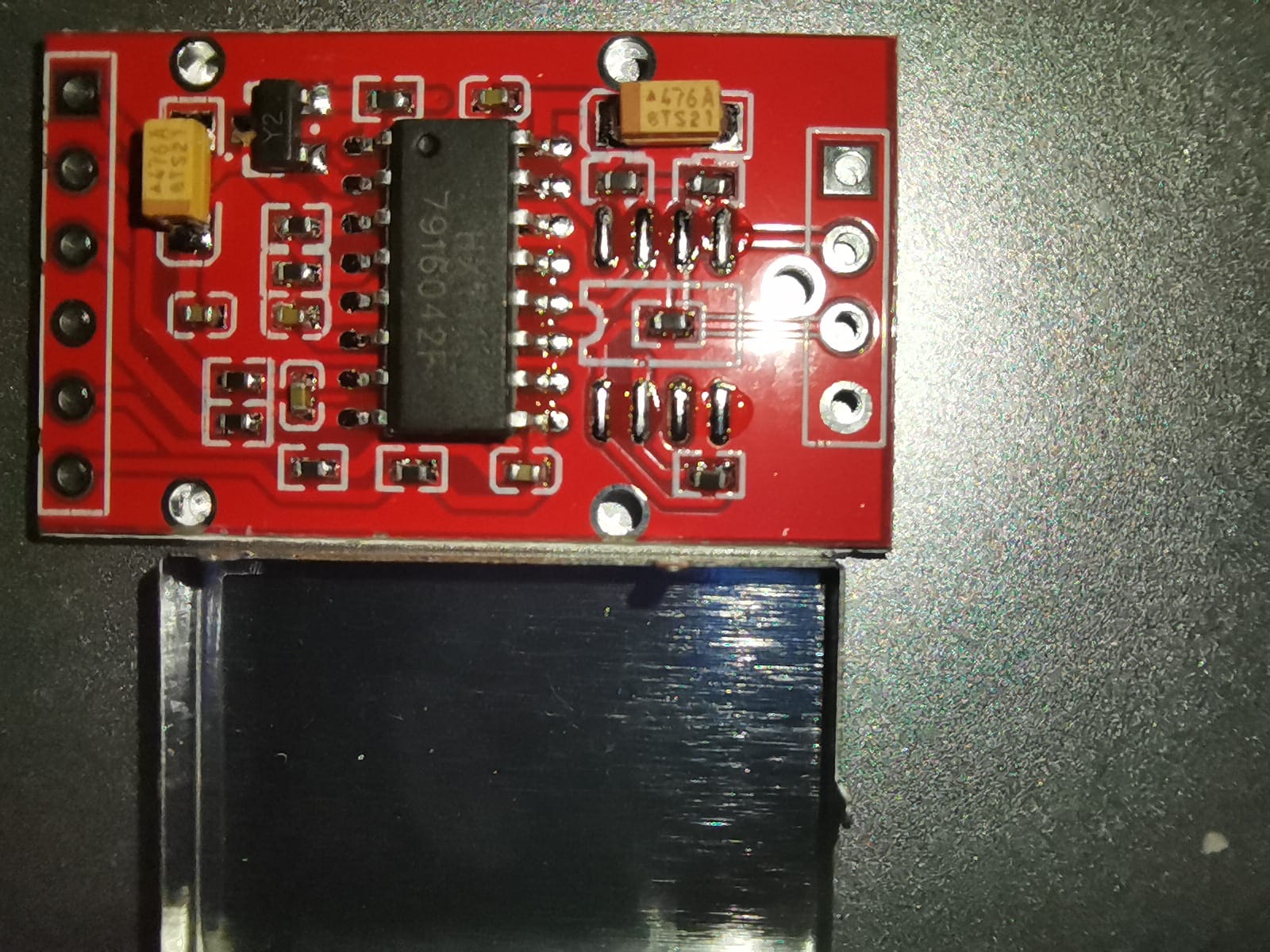
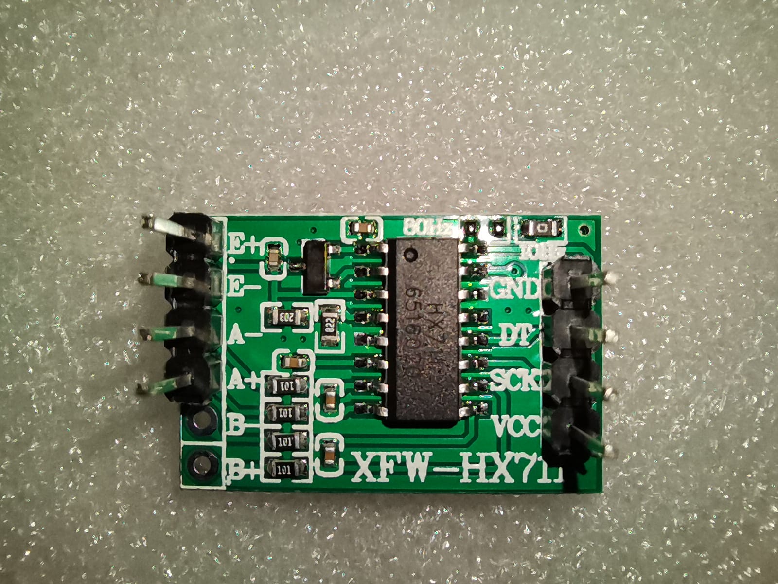
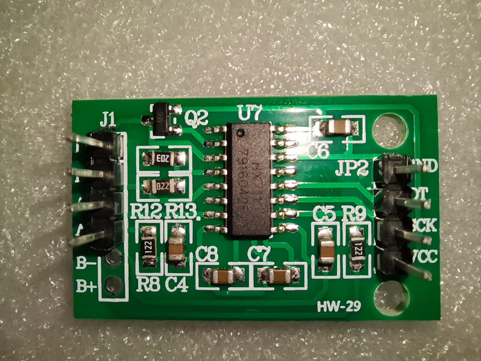
The most significant physical difference between the boards seems to be that Board 1 has no copper ground fill and is not shielded, whereas Board 2 has fill and is shielded.
At 10 sps, Board 2 has significantly better "inputs grounded" resolution than Board 1 (see row 8 ), but with a load cell attached, they have approximately the same resolution (see rows 9 and 10 ). There's one significant exception (see far right column with "24v/MAX" power source).

Notes:
A. ebay seller = kingfull-electronic-company
B. Board 2 has copper ground fill; board 1 has none.
C. Board 2 has metal shield, user-installed
D. Board 1 has the rate pin tied low (with great care, perhaps it could be de-soldered and tied high, to switch it from 10 Hz to 80 Hz.) Board 2 has the rate pin tied high, but it has a jumper that can be soldered closed to take it low.
E. Both HX711 inputs (A- and A+) tied to ground - best case scenario for noise
F. HX711 inputs connected to a four-wire load cell hacked from an American Weigh Scales 200 gr scale; no load on the load cell during sampling.
G. power sources
wall wart = 5v switch-mode power supply
bat/7805 = 9 v battery thru 7805 powers HX711 and 328p
USB = USB power from laptop computer thru FTDI powers both
bat/ADR02 = HX711 powered by 9 v battery through ADR02,
a low-noise regulator by Analog Devices (surface mount);
328p is powered by a 5 v wall wart.
24v/ADR02 = HX711 powered by 24v wall wart through ADR02,
a low-noise regulator by Analog Devices;
328p is powered by a 5 v wall wart.
24v/MAX = HX711 powered by 24v wall wart through MAX6350,
a low-noise reference by Maxim in DIP form, but the
328p is powered by 24v wall wart thru Murata
a 78SR-5/2-C 5v 2amp dc-dc converter. This will be my
my project's power source.
H. the number 2 raised to the power of (NFR load cell); gives the noise free resolution, expressed in terms of the ADC "count" (versus the max achievable = 2^24 =16,777,216), rounded to the nearest thousand.
Abbreviations:
Hz = sloppy for samples per second
n/t = not tested
n/a = not applicable
NFR = Noise-Free Resolution = 24-log(6.6 x rms noise) (log is to base 2)
rms noise = std dev of ADC count
USD = United States dollars
Other remarks:
From the HX711 datasheet: input noise at 10 Hz = 40 uV (rms) and at 80 Hz = 90 uV (rms), so the resolution of board 2 at 80 Hz is expected to be worse (and it is, with the inputs shorted to ground) [see comment, below].
The 328p is on a breadboard and has 0.1uF caps close to the DVCC and AVCC pins. There are also 0.1uF caps and 1 uF tantalum caps on each rail of the breadboard. When using the wall wart, the HX711 was fed thru a 10uH inductor.
Interesting that Board 2 "inputs grounded" resolution is the same regardless of power source.
Comment added much later...shorting inputs to ground violates the common mode range: common mode shouldn't go lower than AGND+1.2v. Not sure what effect that has on the results.