Hello all,
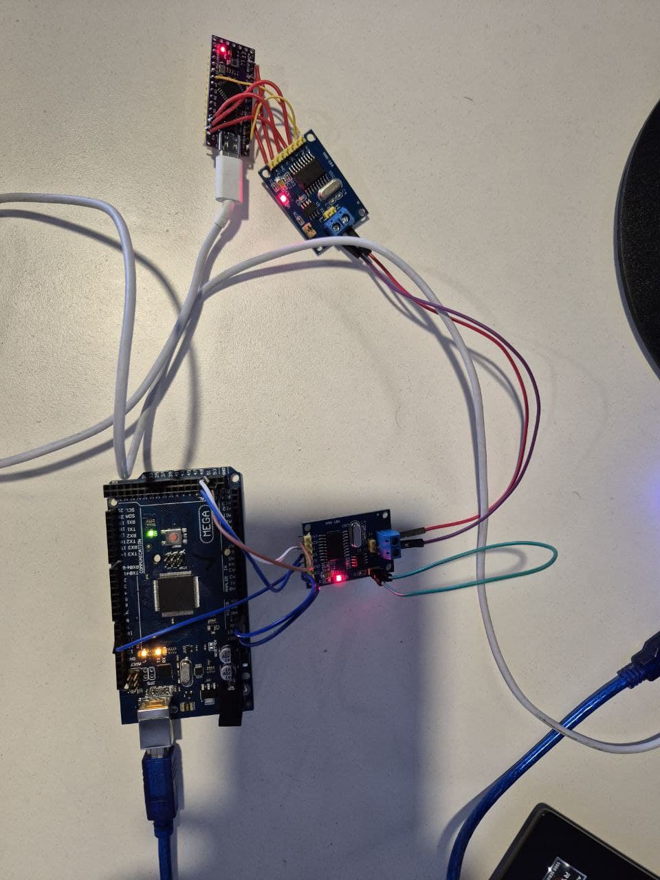
i have two mpc2515 can module. One of them is connected to arduino mega and the other one is connected to arduino nano. I will share the connection and everything. i am trying to send data one to other. The problem is that there is no data received or sent. i dont know what would be the problem here.
Here is the code for receiver (arduino nano):
// CAN Receive Example
//

#include <mcp_can.h>
#include <SPI.h>

long unsigned int rxId;
unsigned char len = 0;
unsigned char rxBuf[8];
char msgString[128];                        // Array to store serial string

#define CAN0_INT 3                             // Set INT to pin 2
MCP_CAN CAN0(10);                               // Set CS to pin 10


void setup()
{
  Serial.begin(115200);

  // Initialize MCP2515 running at 16MHz with a baudrate of 500kb/s and the masks and filters disabled.
  if(CAN0.begin(MCP_ANY, CAN_100KBPS, MCP_8MHZ) == CAN_OK)
    Serial.println("MCP2515 Initialized Successfully!");
  else
    Serial.println("Error Initializing MCP2515...");

  CAN0.setMode(MCP_NORMAL);                     // Set operation mode to normal so the MCP2515 sends acks to received data.

  pinMode(CAN0_INT, INPUT);                            // Configuring pin for /INT input

  Serial.println("MCP2515 Library Receive Example...");
}

void loop()
{
  if(!digitalRead(CAN0_INT))                         // If CAN0_INT pin is low, read receive buffer
  {
    CAN0.readMsgBuf(&rxId, &len, rxBuf);      // Read data: len = data length, buf = data byte(s)

    if((rxId & 0x80000000) == 0x80000000)     // Determine if ID is standard (11 bits) or extended (29 bits)
      sprintf(msgString, "Extended ID: 0x%.8lX  DLC: %1d  Data:", (rxId & 0x1FFFFFFF), len);
    else
      sprintf(msgString, "Standard ID: 0x%.3lX       DLC: %1d  Data:", rxId, len);

    Serial.print(msgString);

    if((rxId & 0x40000000) == 0x40000000){    // Determine if message is a remote request frame.
      sprintf(msgString, " REMOTE REQUEST FRAME");
      Serial.print(msgString);
    } else {
      for(byte i = 0; i<len; i++){
        sprintf(msgString, " 0x%.2X", rxBuf[i]);
        Serial.print(msgString);
      }
    }

    Serial.println();
  }
}

/*********************************************************************************************************
  END FILE
*********************************************************************************************************/
here is the transmitter (arduino mega):
// CAN Send Example
//

#include <mcp_can.h>
#include <SPI.h>

MCP_CAN CAN0(10);     // Set CS to pin 10

void setup()
{
  Serial.begin(115200);

  // Initialize MCP2515 running at 16MHz with a baudrate of 500kb/s and the masks and filters disabled.
  if(CAN0.begin(MCP_ANY, CAN_100KBPS, MCP_8MHZ) == CAN_OK) Serial.println("MCP2515 Initialized Successfully!");
  else Serial.println("Error Initializing MCP2515...");

  CAN0.setMode(MCP_NORMAL);   // Change to normal mode to allow messages to be transmitted
}

byte data[8] = {0x00, 0x01, 0x02, 0x03, 0x04, 0x05, 0x06, 0x07};

void loop()
{
  // send data:  ID = 0x100, Standard CAN Frame, Data length = 8 bytes, 'data' = array of data bytes to send
  byte sndStat = CAN0.sendMsgBuf(0x100, 0, 8, data);
  if(sndStat == CAN_OK){
    Serial.println("Message Sent Successfully!");
  } else {
    Serial.println("Error Sending Message...");
  }
  delay(100);   // send data per 100ms
}

/*********************************************************************************************************
  END FILE
*********************************************************************************************************/
transmitter mega output:
Error Sending Message...
Error Sending Message...
Error Sending Message...
receiver nano output:
Entering Configuration Mode Successful!
Setting Baudrate Successful!
MCP2515 Initialized Successfully!
MCP2515 Library Receive Example...
the modules have 8MHz crystal and i tried with different speeds. also i removed the jumpers and i tried without terminal resistor (i hoped that it will work but didnt) .