I cant get my NRf24's to work

I am trying to get a Nano and an Uno to communicate via NRf24's but I can't seem to get it to work.

I have been looking for answers for this for the last two days but i cant find anything so now im asking here.

I have tried four different Tutorials trying to get my Nano to wirelessly send a hello world to my Uno but it has never worked.

I have 3 NRF24Lo1+ modules and I've tried this with all of them in every possible combination.

I have added some Serial-println lines as so i can watch the serial monitor and see if the programm is running correctly and as far as I can tell nothing is wrong there. (I would try some of my other Nano's but my soldering Iron broke and i cant seem to get the cables to connect reliably by just putting them in the holes)

Another Uno is in the mail and should arrive tomorrow so I can test it with that then but I really dont think either of the arduinos is damaged as they have no problems with any other sketches I upload to them.

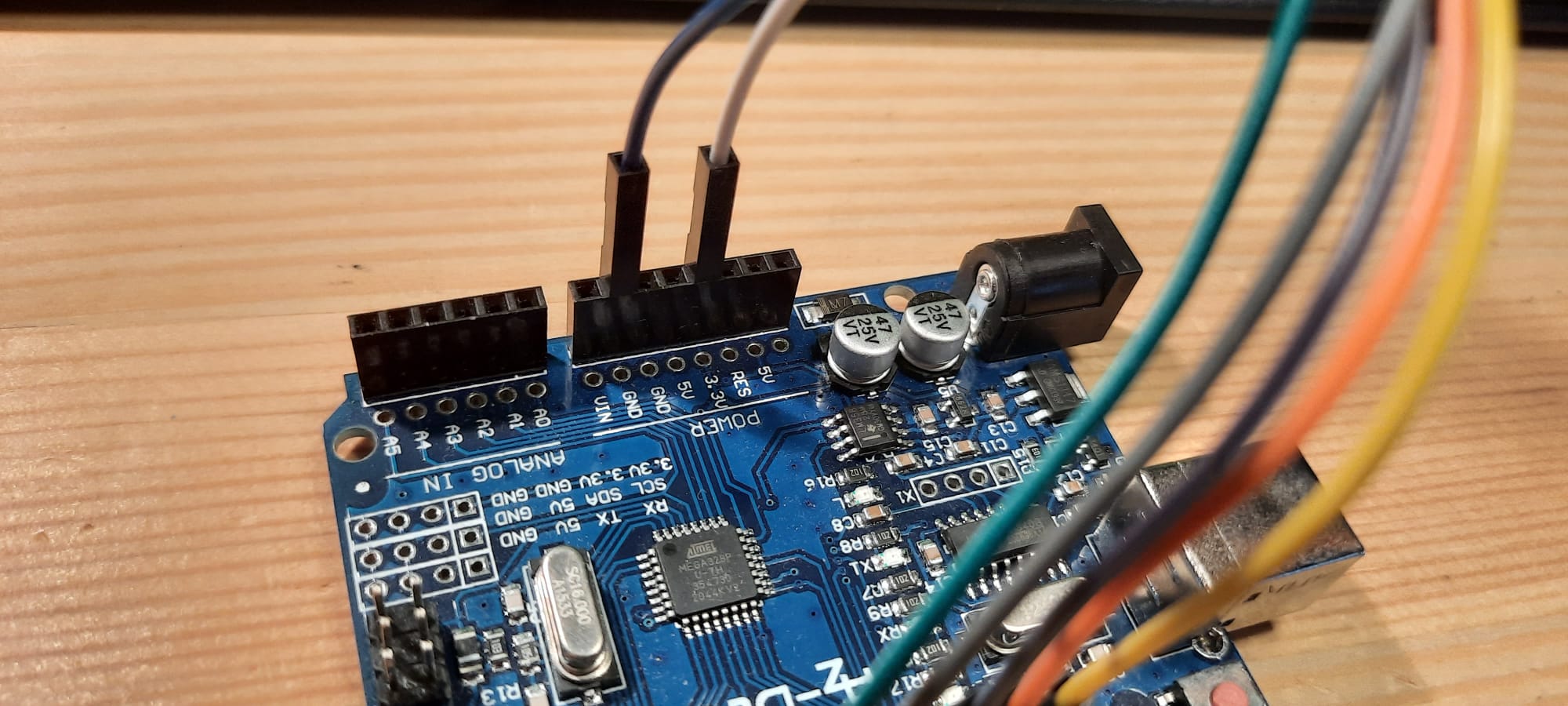
My Arduinos and my NRf24's are from AZ-Delivery and I have properly installed the needed USB-drivers.

This is the first Tutorial I followed:
HowToMechatronicsTutorial
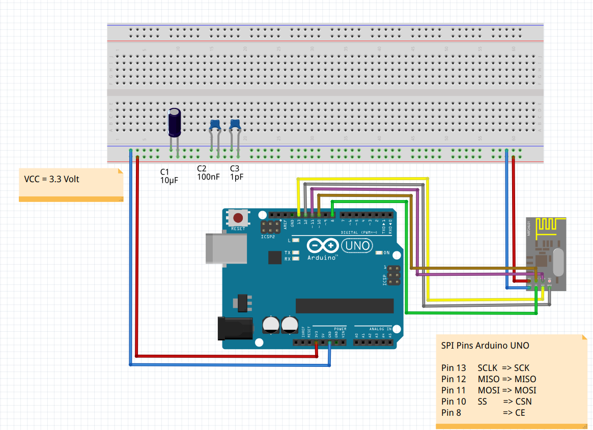
I am aware that the SPI pins of the Mega and the Uno are different I have connected mine correctly.
This tutorial also gives the wrong SPI-pins for the Nano, which i have also connected correctly

The code from this Tutorial is the one I modified with the Serial.println()

My Transmitter Code (running on the Nano):

/*
* Arduino Wireless Communication Tutorial
*     Example 1 - Transmitter Code
*                
* by Dejan Nedelkovski, www.HowToMechatronics.com
* 
* Library: TMRh20/RF24, https://github.com/tmrh20/RF24/
*/
#include <SPI.h>
#include <nRF24L01.h>
#include <RF24.h>

RF24 radio(7, 8); // CE, CSN

const byte address[6] = "00001";

void setup() {

  Serial.begin(9600);
  radio.begin();
  radio.openWritingPipe(address);
  radio.setPALevel(RF24_PA_MIN);
  radio.stopListening();
  Serial.println ("Setup Done");
}
void loop() {
  const char text[] = "Hello World";
  Serial.println("text set");
  radio.write(&text, sizeof(text));
  Serial.println("Message sent");
  delay(1000);
}

This is what appears in the Serial Monitor:

13:13:59.285 -> Setup Done
13:13:59.285 -> text set
13:13:59.331 -> Message sent
13:14:00.300 -> text set
13:14:00.347 -> Message sent
13:14:01.318 -> text set
13:14:01.364 -> Message sent
13:14:02.379 -> text set
13:14:02.379 -> Message sent
13:14:03.392 -> text set
13:14:03.439 -> Message sent
13:14:04.406 -> text set
13:14:04.452 -> Message sent

As you can see this is looking excatly as it is supposed to do

This is my Receiver Code (running on the Uno):

/*
* Arduino Wireless Communication Tutorial
*       Example 1 - Receiver Code
*                
* by Dejan Nedelkovski, www.HowToMechatronics.com
* 
* Library: TMRh20/RF24, https://github.com/tmrh20/RF24/
*/
#include <SPI.h>
#include <nRF24L01.h>
#include <RF24.h>

RF24 radio(7, 8 ); // CE, CSN

const byte address[6] = "00001";

void setup() {
  Serial.begin(9600);
  radio.begin();
  radio.openReadingPipe(0, address);
  radio.setPALevel(RF24_PA_MIN);
  radio.startListening();
  Serial.println("Setup Done");
}
void loop() {
  if (radio.available()) {
    Serial.println("Data received");
    char text[32] = "";
    radio.read(&text, sizeof(text));
    Serial.println(text);
    Serial.println("cycle complete");
  }
  Serial.println("loop running");
}

This appears in the Serial Monitor:

13:17:17.529 -> Setup Done
13:17:17.529 -> loop running
13:17:17.576 -> loop running
13:17:17.622 -> loop running

Here we can see that the loop is running but it doesn't detect anything over wireless so it doesn't write "Data received" or "cycle complete"

This is the second Tutorial:
InstructablesCurcuitsTutorial
The Code they have listed for the receiver needed a few more brackets before it was able to be compiled but then it uploaded without a Problem but it still didn't work

The third Tutorial:
I cant find it anymore but I do remember that the Code wouldn't compile and I couldn't fix it.

The fourth Tutorial:
I used the Code from a post in this Forum which supposedly works: ForumPost

The Server Code results in this in the Serial Monitor:

13:30:12.790 -> init failed
13:30:12.883 -> Sent data
13:30:15.003 -> Sent data
13:30:17.075 -> Sent data
13:30:19.197 -> Sent data
13:30:21.271 -> Sent data
13:30:23.393 -> Sent data
13:30:25.466 -> Sent data
13:30:27.585 -> Sent data

The Client Code results in this in the Serial Monitor:

13:33:31.459 -> init failed
13:33:36.487 -> No message, is nrf24_server running?
13:33:41.509 -> No message, is nrf24_server running?
13:33:46.490 -> No message, is nrf24_server running?
13:33:51.509 -> No message, is nrf24_server running?

I have installed all the libraries required by the sketches.
I am relatively new to arduino so please assume that I made every possible stupid mistake.

Thanks in advance

I'll put all the things I already checked for because of suggestions from here in this List (as long as I can edit my post of course):
/

How are the radio modules powered? The number one problem when using those radios is lack of current capability of the radio power supplies. The 3.3V regulators on Uno, Nano, Mega simply can't supply the required current. Try adding a 10uF to 100uF cap across the rf24 power pins. I use homemade copies of these rf24 adapter modules with great success.

The tutorial that I used to get my radios to work is the simple rf24 tutorial by Robin2. I tried many other tutorials and code from the net with no success, but this code actually worked. It covers the power problem as well as some other common problems. There is a sketch (see reply #30) that will test the physical connection between the radio module and its processor.

Post photos of your wiring.

Where were you when I was trying to figure that one out a few years ago? Took me 2 days to consider power requirements.
I always thought the NRf24 should have a brownout LED.

1 Like

This is the wiring on the nano:


This is the wiring on the uno:


There actually was a wiring mistake on the Uno: Pin12 is supposed to got to Miso but it went to IRQ on the module. This probably appeared while switching the modules around.
Still wont work though :frowning:

Edit: I have ordered some of these adapterboards since I dont have any Caps here right now

I never had a problem testing them when powered by TWO AA cells.
Paul

I got those nRF24L01 to work using the RadioHead library.

RadioHead Library

I also used 10uF, 100nF and 1pF capacitors to stabilize the 3.3V power supply of the Arduino. Nevertheless I made even a better experience using a 3.3V voltage regulator.

Code Client

// nrf24_client

#include <SPI.h>
#include <RH_NRF24.h>
int dt = 5000;

// Singleton instance of the radio driver
RH_NRF24 nrf24;
// RH_NRF24 nrf24(8, 7); // use this to be electrically compatible with Mirf
// RH_NRF24 nrf24(8, 10);// For Leonardo, need explicit SS pin
// RH_NRF24 nrf24(8, 7); // For RFM73 on Anarduino Mini

void setup() 
{
  Serial.begin(9600);
  while (!Serial) 
    ; // wait for serial port to connect. Needed for Leonardo only
  if (!nrf24.init())
    Serial.println("init failed");
  // Defaults after init are 2.402 GHz (channel 2), 2Mbps, 0dBm
  if (!nrf24.setChannel(1))
    Serial.println("setChannel failed");
  if (!nrf24.setRF(RH_NRF24::DataRate2Mbps, RH_NRF24::TransmitPower0dBm))
    Serial.println("setRF failed");    
}


void loop()
{
  Serial.println("Sending to nrf24_server");
  
  // Send a message to nrf24_server
  char data[] = "Hello World!";

//  for(int i=0; i<=sizeof(data); i++){
//    Serial.print(char(data[i]));
//  }
//
//  Serial.println("");
  
  nrf24.send(data, sizeof(data));
  nrf24.waitPacketSent();
  
  // Now wait for a reply
  char buf[RH_NRF24_MAX_MESSAGE_LEN];
  char len = sizeof(buf);

  if (nrf24.waitAvailableTimeout(500))
  { 
    // Should be a reply message for us now   
    if (nrf24.recv(buf, &len))
    {
      Serial.print("got reply: ");
      Serial.println((char*)buf);
    }
    else
    {
      Serial.println("recv failed");
    }
  }
  else
  {
    Serial.println("No reply, is nrf24_server running?");
  }
  delay(dt);
}

Code Server

// nrf24_server

#include <SPI.h>
#include <RH_NRF24.h>

// Singleton instance of the radio driver
RH_NRF24 nrf24;
// RH_NRF24 nrf24(8, 7); // use this to be electrically compatible with Mirf
// RH_NRF24 nrf24(8, 10);// For Leonardo, need explicit SS pin
// RH_NRF24 nrf24(8, 7); // For RFM73 on Anarduino Mini

void setup() 
{
  Serial.begin(9600);
  while (!Serial) 
    ; // wait for serial port to connect. Needed for Leonardo only
  if (!nrf24.init())
    Serial.println("init failed");
  // Defaults after init are 2.402 GHz (channel 2), 2Mbps, 0dBm
  if (!nrf24.setChannel(1))
    Serial.println("setChannel failed");
  if (!nrf24.setRF(RH_NRF24::DataRate2Mbps, RH_NRF24::TransmitPower0dBm))
    Serial.println("setRF failed");    
}

void loop()
{
  if (nrf24.available())
  {
    // Should be a message for us now   
    char buf[RH_NRF24_MAX_MESSAGE_LEN];
    char len = sizeof(buf);
    if (nrf24.recv(buf, &len))
    {
//      NRF24::printBuffer("request: ", buf, len);
      Serial.print("got request: ");
      Serial.println((char*)buf);
      
      // Send a reply
      char data[] = "And hello back to you";
      nrf24.send(data, sizeof(data));
      nrf24.waitPacketSent();
      Serial.println("Sent a reply");
    }
    else
    {
      Serial.println("recv failed");
    }
  }
}

NRF24L01_Client_Char.ino (1,5 KB)
NRF24L01_Server_Char.ino (1,3 KB)


@groundFungus
Ok I am now using the modified Code from Tutorial 1 (The one I posted here) with the nrf24's mounted on the adapter modules like you suggested

This is what appears in the serial monitor of the receiver:

20:30:45.697 -> Data received
20:30:45.697 ->
20:30:45.743 -> cycle complete
20:30:45.743 -> loop running
20:30:45.743 -> Data received
20:30:45.789 ->
20:30:45.789 -> cycle complete
20:30:45.835 -> loop running
20:30:45.835 -> Data received
20:30:45.835 ->
20:30:45.835 -> cycle complete
20:30:45.835 -> loop running

what i'm getting from this is that the Receiver gets the message and starts following the Code in the if statement but for some reason the content of the message doesn't get put into the variable and so it prints an empty line, or maybe the message was empty from the beginning?

I tried adding some delays in there in case it was printing before the content was completly written into the variable (dont know if that is even a possible issue but it was the only thing I could think of) but that didn't change anything.

1 pF? Seriously? :face_with_raised_eyebrow:

The Adapters appear to have made a difference. The receiver part is behaving as if radio.available() is always returning true, assuming you have not edited the console output. This could indicate a wiring error on the receiver. Try completely removing the nrf24l01 from the adapter on the receiver to see if you get exactly the same effect. Another trouble shooting step would be to swap the roles of the uno and nano between transmitter and receiver.
You seem to be discovering an alarming number of errors in the tutorials you have tried.

And perhaps fix the soldering of the pins to that poor nano. I'd be surprised if all of those contacts proved to be reliable.

1 Like

doin that right now. My old soldering Iron was dying a slow death while i was making those and the new one just arrived yesterday

Have you tried the connection test sketch from Robin2's simple rf24 tutorial? See reply #2.

I finally had time to do all the things that were suggested here.

@anon35827816: I resoldered some of the connections on the nano and I am now 99% certain that they all provide a reliable connection

@6v6gt: It is in fact the case that the Serial Monitor output stays the same when removing the nrf24l01 from the adapter, however: I tried this with all 5 of my adapters and nothing changed. I find it hard to believe that all of my adapters are DOA.
I also tried switching the arduinos without success. I even did the adapter test on my second Uno with the same results.

yes the tutorial does seem to have quite the number of errors but as far as I can tell none of them seem to be a major Error but instead consist of the author giving a number of a pin that is only of by one.
This and the many comments under the video explanation thanking the author for the tutorial made me follow it.
Also, having nothing to do yesterday, I went through the tutorial's code while double checking with the documentation of the library and to me it seems that the code should work fine.

(I know that I am basically excluding hardware And software as the reason for the failure here but then again: that's why I'm asking here)

@groundFungus: I have tried that one but as far as I can tell it looks ok??

This is what comes up with the Uno:

20:31:01.130 -> CheckConnection Starting
20:31:02.741 ->
20:31:02.741 -> FIRST WITH THE DEFAULT ADDRESSES after power on
20:31:02.833 -> Note that RF24 does NOT reset when Arduino resets - only when power is removed
20:31:02.879 -> If the numbers are mostly 0x00 or 0xff it means that the Arduino is not
20:31:02.970 -> communicating with the nRF24
20:31:03.016 ->
20:31:03.016 -> SPI Speedz = 10 Mhz
20:31:03.062 -> STATUS = 0x06 RX_DR=0 TX_DS=0 MAX_RT=0 RX_P_NO=3 TX_FULL=0
20:31:03.108 -> RX_ADDR_P0-1 = 0xe3e3e3e363 0x0000003800
20:31:03.153 -> RX_ADDR_P2-5 = 0x41 0x40 0x40 0x42
20:31:03.199 -> TX_ADDR = 0xe3e3e3e363
20:31:03.199 -> RX_PW_P0-6 = 0x00 0x00 0x00 0x00 0x00 0x00
20:31:03.245 -> EN_AA = 0x1f
20:31:03.292 -> EN_RXADDR = 0x01
20:31:03.292 -> RF_CH = 0x04
20:31:03.292 -> RF_SETUP = 0x00
20:31:03.292 -> CONFIG = 0x02
20:31:03.337 -> DYNPD/FEATURE = 0x00 0x00
20:31:03.337 -> Data Rate = 1 MBPS
20:31:03.384 -> Model = nRF24L01+
20:31:03.429 -> CRC Length = 8 bits
20:31:03.429 -> PA Power = PA_MIN
20:31:03.429 -> ARC = 0
20:31:03.429 ->
20:31:03.429 ->
20:31:03.429 -> AND NOW WITH ADDRESS AAAxR 0x41 41 41 78 52 ON P1
20:31:03.522 -> and 250KBPS data rate
20:31:03.522 ->
20:31:03.522 -> SPI Speedz = 10 Mhz
20:31:03.568 -> STATUS = 0x06 RX_DR=0 TX_DS=0 MAX_RT=0 RX_P_NO=3 TX_FULL=0
20:31:03.614 -> RX_ADDR_P0-1 = 0xe3e3e3e363 0x0000003800
20:31:03.661 -> RX_ADDR_P2-5 = 0x41 0x40 0x40 0x42
20:31:03.707 -> TX_ADDR = 0xe3e3e3e363
20:31:03.753 -> RX_PW_P0-6 = 0x00 0x00 0x00 0x00 0x00 0x00
20:31:03.799 -> EN_AA = 0x1f
20:31:03.799 -> EN_RXADDR = 0x01
20:31:03.799 -> RF_CH = 0x04
20:31:03.846 -> RF_SETUP = 0x00
20:31:03.846 -> CONFIG = 0x02
20:31:03.892 -> DYNPD/FEATURE = 0x00 0x00
20:31:03.892 -> Data Rate = 1 MBPS
20:31:03.892 -> Model = nRF24L01+
20:31:03.938 -> CRC Length = 8 bits
20:31:03.938 -> PA Power = PA_MIN
20:31:03.984 -> ARC = 0

I am not good at reading this but it seems that:
The RX_PW_P0-6 seems to return only 0x00.
RF_Setup and DYNPD/FEATURE also only return 0x00 but they only give 1 or 2 returns so I don't know how significant that is.

And this comes up with the nano:

20:42:43.472 -> CheckConnection Starting
20:42:43.472 ->
20:42:43.472 -> FIRST WITH THE DEFAULT ADDRESSES after power on
20:42:43.518 -> Note that RF24 does NOT reset when Arduino resets - only when power is removed
20:42:43.610 -> If the numbers are mostly 0x00 or 0xff it means that the Arduino is not
20:42:43.703 -> communicating with the nRF24
20:42:43.703 ->
20:42:43.703 -> SPI Speedz = 10 Mhz
20:42:43.749 -> STATUS = 0x06 RX_DR=0 TX_DS=0 MAX_RT=0 RX_P_NO=3 TX_FULL=0
20:42:43.841 -> RX_ADDR_P0-1 = 0x0000000006 0xc0c0c0c0c0
20:42:43.841 -> RX_ADDR_P2-5 = 0x06 0xc0 0x06 0xc2
20:42:43.887 -> TX_ADDR = 0x0000000006
20:42:43.933 -> RX_PW_P0-6 = 0x00 0x06 0x00 0x06 0x00 0x06
20:42:43.933 -> EN_AA = 0x1f
20:42:43.979 -> EN_RXADDR = 0x06
20:42:43.979 -> RF_CH = 0x04
20:42:44.025 -> RF_SETUP = 0x06
20:42:44.025 -> CONFIG = 0x06
20:42:44.071 -> DYNPD/FEATURE = 0x06 0x00
20:42:44.071 -> Data Rate = 1 MBPS
20:42:44.071 -> Model = nRF24L01+
20:42:44.117 -> CRC Length = 16 bits
20:42:44.117 -> PA Power = PA_MAX
20:42:44.163 -> ARC = 6
20:42:44.163 ->
20:42:44.163 ->
20:42:44.163 -> AND NOW WITH ADDRESS AAAxR 0x41 41 41 78 52 ON P1
20:42:44.209 -> and 250KBPS data rate
20:42:44.256 ->
20:42:44.256 -> SPI Speedz = 10 Mhz
20:42:44.302 -> STATUS = 0x06 RX_DR=0 TX_DS=0 MAX_RT=0 RX_P_NO=3 TX_FULL=0
20:42:44.302 -> RX_ADDR_P0-1 = 0x0000000006 0xc0c0c0c000
20:42:44.394 -> RX_ADDR_P2-5 = 0x06 0xc0 0x06 0xc2
20:42:44.440 -> TX_ADDR = 0x0000000006
20:42:44.440 -> RX_PW_P0-6 = 0x00 0x06 0x00 0x06 0x00 0x06
20:42:44.486 -> EN_AA = 0x1f
20:42:44.532 -> EN_RXADDR = 0x06
20:42:44.532 -> RF_CH = 0x04
20:42:44.532 -> RF_SETUP = 0x06
20:42:44.532 -> CONFIG = 0x06
20:42:44.578 -> DYNPD/FEATURE = 0x06 0x00
20:42:44.578 -> Data Rate = 1 MBPS
20:42:44.624 -> Model = nRF24L01+
20:42:44.670 -> CRC Length = 16 bits
20:42:44.670 -> PA Power = PA_MAX
20:42:44.670 -> ARC = 6
20:42:44.670 ->
20:42:44.670 ->

I'm gonna put the Transmitter and Receiver Code I used for testing @6v6gt's recommendations here again in case I accidentally changed an important part of it.

Transmitter:

/*
* Arduino Wireless Communication Tutorial
*     Example 1 - Transmitter Code
*                
* by Dejan Nedelkovski, www.HowToMechatronics.com
* 
* Library: TMRh20/RF24, https://github.com/tmrh20/RF24/
*/
#include <SPI.h>
#include <nRF24L01.h>
#include <RF24.h>

RF24 radio(7, 8); // CE, CSN

const byte address[6] = "00001";

void setup() {

  Serial.begin(9600);
  radio.begin();
  radio.openWritingPipe(address);
  radio.setPALevel(RF24_PA_MIN);
  radio.stopListening();
  Serial.println ("Setup Done");
}
void loop() {
  const char text[] = "HW";
  Serial.println("text set");
  radio.write(&text, 2);
  Serial.print("Message sent:");
  Serial.println(text);
  delay(1000);
}

Receiver:

/*
* Arduino Wireless Communication Tutorial
*       Example 1 - Receiver Code
*                
* by Dejan Nedelkovski, www.HowToMechatronics.com
* 
* Library: TMRh20/RF24, https://github.com/tmrh20/RF24/
*/
#include <SPI.h>
#include <nRF24L01.h>
#include <RF24.h>

RF24 radio(7, 8 ); // CE, CSN

const byte address[6] = "00001";

void setup() {
  Serial.begin(9600);
  radio.begin();
  radio.openReadingPipe(0, address);
  radio.setPALevel(RF24_PA_MIN);
  radio.startListening();
  Serial.println("Setup Done");
}
void loop() {
  if (radio.available()) {
    Serial.println("Data received");
    char text[32] = "";
    radio.read(&text, 2);
    Serial.println("Data read");
    Serial.println(text);
    Serial.println("cycle complete");
  }
  Serial.println("loop running");
}

As far as I know the connection tests are OK.

The code in reply #15 works on my setup. Unos with low power rf24 modules powered by homemade rf24 adapters.

How far apart are the modules while you are testing? The high power modules (with external antennae) should be at least a couple of meters apart (even with RF24_PA_MIN power).

@groundFungus
I am using these
module-nrf24l01
mounted on these:
Download
and they are like 10 to 20 cm apart when i am testing them.
that should be a good distance for these small antennae right?

If it works for you it must be a Hardware Issue on my side right?

I'm gonna try using only the power pins from the adapterboards and connecting the other pins directly to the arduino and use Uno's for both this time to completely exclude the possibility of my soldering being the Issue. Maybe this way I can take advantage of the power stabilisation without having radio.available() always return true.

I have also ordered a few of these so I can cut out the seemingly faulty adapterboards completely.

so I have just run the receiver code on a Uno with the adapterboard only used to stabillise the power and the Data pins connected directly to the arduino and I am still getting a running Loop that writes empty lines into the serialmonitor.
This happens on both of my uno's.

I dont understand how an Adapterboard with no nrf24 in it and a nrf24 with no adapterboard connected to any of the Data pins, can have the same error?

Hey, I think it is something(bug) in the Arduino IDE itself!
I have had similar isseus. I created a program some years ago (in IDE version 1.6.0) that always worked fine.
Now when I compile and upload this exact program with the latest 1.8.xx version of the IDE the slave/reciever Arduino nano simply freezes after the first command was send to the master.
when I de-install 1.8.xx and reinstall 1.6.0 and compile again with the exact same library's it runs flawless. I spend hours to find out why it is not working, but finaly decided that is is simply easier to use 1.6.0 whenever I need to alter the program :roll_eyes:

Or maybe update the IDE and the NRF24 Libraries, then all the examples provide by the Libraries should work.

You might have a dependancy in your old code and libraries that requires you to use the older versions.

I tried with IDE 1.8.15 and RF24-1.4.1 lib. which are to my knowldedge the latest versions. And that makes the Arduino freeze. have to choose the nano and processor " ATmega328P (old bootloader)"

the setup runs fine the AckPayload that is loaded ends up at the master.

void setup() {
  // Serial.begin(9600);
  // Serial.println ("Start");
  for (int i = 0; i < 5; i++)
    EEpromNodeAddress[i] = EEPROM.read(i);

  // --------------------------- RADIO SETUP CONFIGURATION AND SETTINGS -------------------------//
  radio.begin();
  radio.setPALevel(RF24_PA_HIGH);         // set power level of the radio
  radio.setDataRate(RF24_250KBPS);        // set RF datarate
  radio.setChannel(0x76);                 // set radio channel to use - ensure it matches the target host
  radio.setRetries(15, 15);               // set time between retries and max no. of retries
  radio.openReadingPipe(1, EEpromNodeAddress);  // open a reading pipe on the chosen address - matches the master tx
  radio.enableAckPayload();               // enable ack payload - slave replies with data using this feature
  radio.writeAckPayload(1, &ReplyData, sizeof(ReplyData)); // preload the payload with initial data - sent after an incoming message is read
  radio.startListening();
  // --------------------------------------------------------------------------------------------//

Then from the loop, the folowing function is called;

void radioCheckAndReply(void) {
  // check for radio message and send sensor data using auto-ack
  if (radio.available())  {
    radio.writeAckPayload(1,&ReplyData, sizeof(ReplyData));
    radio.read(&NewTargets, sizeof(NewTargets) );
    Tank1Valve[5] = NewTargets[1];
    Tank2Valve[5] = NewTargets[2];
    Tank3Valve[5] = NewTargets[3];
  }

As soon as the radio.writeAckPayload(1,&ReplyData, sizeof(ReplyData)); is execuded the program freezes.

The 1.6.0 IDE works with both the older and newer versions of the Libraries.

And do the examples, in the RF24 library, that use writeAckPayload work OK ?