I used to have this years ago, sold it for money but now I miss having it. Authentic version is very expensive these days so I thought I'd try to fake one for my man cave.
The yellow part goes from steady to random sparkling, that would be easily done with MAX7219 and bunch of regular yellow LEDs. I am thinking of making the yellow part run independently of the rest of the sign with a single ATTiny85. I've made random sparkling part before.
3mm red/white LED with common pin can be found on Aliexpress. Digikey and Mouser costs more and only as SMD, not through hole or panel mount. I guess red and white is an uncommon combination, possible due to voltage difference (about 2v and 3v). I do plan to drive white LED much lower so I don't get blinded!
I might use 2 separate AVR chips for red/white, one chip to handle the oval with fading and one pin to signal second AVR chip (same way a push button would work) to start random white sparkle for Nintendo logo. That way both the logo and oval seems to run at the same time like the video above. A possibility with MAX7219 on Nintendo logo is to wire them with column of red, then white while common cathode to rows (white will be undervolted), Logo display's sparkle mode can be toggled on when the master AVR chip sends start, it'll sparkles for a few seconds then go back to red. When it goes back to red, it goes back to checking the input pin for a signal from master AVR
But I am not sure about the rest. The oval part is steady red, then chasing with faded white light on leading and trailing ends. Maybe a way to simulate fading red and white in the oval area but no single chip has a few hundred PWM pins and I have no experience with intelligent communication between multiple AVR chips for handling the whole oval lights.
Can you guys give me an idea that I could try to work from here? Also I have not bought any LED yet as I don't have a number yet, would common anode or common cathode work better?
EDIT if you're wondering how the original sign worked, here's a video of a similar Nintendo sign: Let's Repair Your Nintendo Fiber-Optic Sign! - YouTube the difference is it's 2 sided and has additional sparkling background but same technology.
dave-in-nj:
do you have a link to the light and motor mechanism ?
no, my old sign used 110v ac motor that was geared down to (I think) about 20 RPM, and a 75w halogen light. The color wheel did provide fixed pattern that only seemed random. With the replica I want to make using LED, it'd be truly random sparkly
MAX7219 can do 64 single LEDs per output, if their Vf < 2.5V than you can use 2 in series.
You can have all the MAX7219s you want.
Either connect them in series, which can complicate the programming, or connect them in parallel, with each having its own chip select, and sharing clock and data.
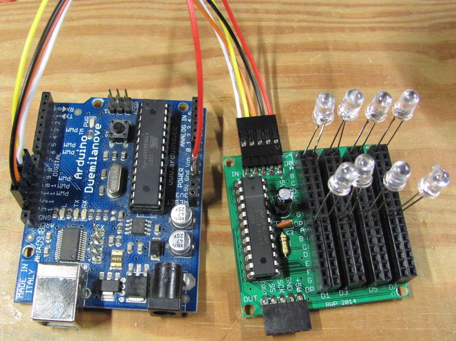
For example, I used 4 in this project, with SPI.transfer to send data to each one, each on it's chip select line.
Or you can connect up 64 individual LEDs, like I did here
Maybe easier using WS2812B individually addressable LEDs. The sign appears to change colour (at least the red part), not that easy to do with RGB LEDs and MAX7912 drivers.