World Map with over 200 Leds (Max. 1280)

Hello. This project involves upgrading a big world map I made for my family that had individually non lit colored pins for each major city we've visited. The colors have since faded and it needs a refresh.
We are four people in my family so the old map had four colors for each person, and one color local cities in our country. So, it's five colors, over 200 pins. I want to have each pinhead with small leds. Also, an arduino project would help me solve some technical issues I believe exist. If everything goes well I have some ideas about how to extend it, interactivity, IoT, world domination, etc.

I've made this thread for documenting my progress with information I've gathered and used on functional tests. At the moment this very much a solo project but I'd be happy to read your thought and ideas. It has been years since I've programmed and soldered. Even this duemilanove I have has been sitting in a box for about 15 years. I'm getting back into it, so, let's get to it.

Functional Arduino tests.

In total I need a bit over 200 leds that have to light up on command. Doing over 200 leds with just one old arduino and no planning may add complexity and have excessive power requirements. I've searched the web for information on doing this and I've decided on the following solution:
One Arduino (in my case a Duemilanove) in which 5 PWM pins are used to control 6 MAX7219, with 64 leds possible each. Using this solution also makes it possible to "address" each led individually (which is awesome!). One person in the family will need two MAX7219, the rest one. I believe this is the best way I can debug the project if needed.

Here is a test:

Don't know how to upload videos yet, GIF in the meantime.
z1-65jwhaw

This is a test of the sorted out pins for the 1088AS 8x8 led matrix. So I can individually wire them and put them on the map.
20240607_114655_enc

Wiring reference:

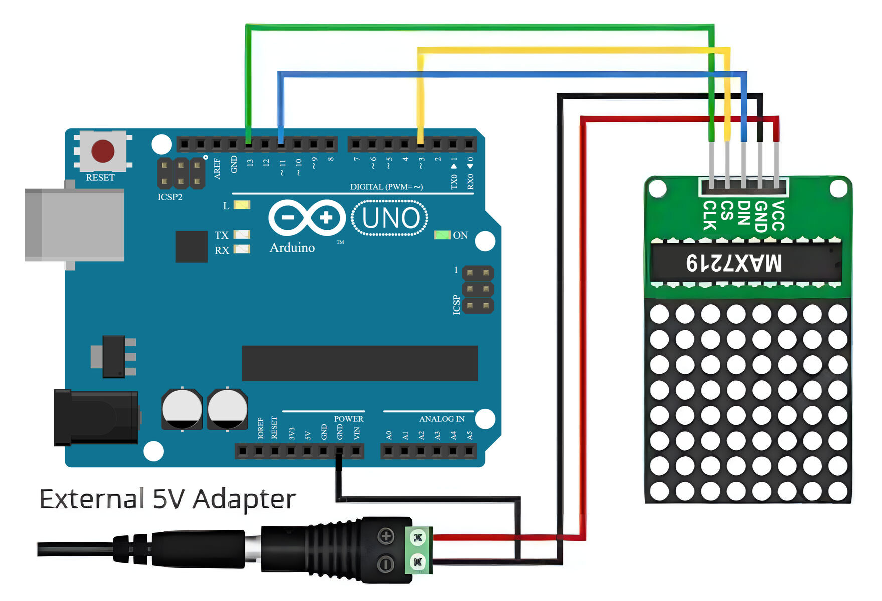
This is a flicker test for MAX7219 with a big 8x8 led matrix. I despise flickering leds but it will be ok. Of course, the small 0402s will behave slightly different.
20240607_125026_enc

Sorting out the mess that are 1088as pins.
The MAX7219 modules that I bought come with a 1088as 8x8 led matrix. I was not expecting the pin organization to be confusing and initially all I got were weird lines that made no sense. After much googling I found this video:

simplyput2796 explained the pins organization extremely well and, thanks to him, I made this and I'd like to share it with you. With this organization the 8x8 led matrix will be right side up. Also, it turns out a lot of this "decoding" can be found in the MD_MAX72xx_lib.h from the "MD_MAX72xx Arduino library" but I was not ready to read it at the time.

MAX7219 with custom "decoded" 1080as. According to simplyput2796 using hex digit with one character is easier and I agree.


MAX7219 with custom "decoded" 1080as with fancy photos for future reference

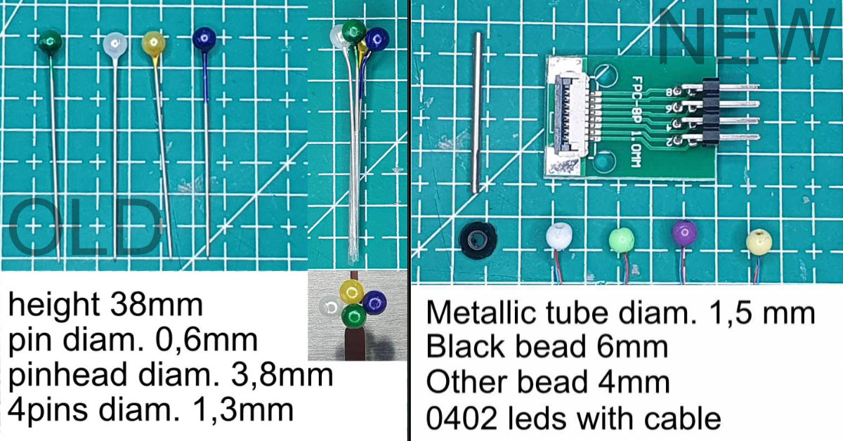
Light pins. Old and New


Working test if the light pins:
Pins_003-Test

Comparison between the old and the new pins with 0403 leds. The black one is for support and it is all fixed in place with UV resin:

1 Like

APA106 individually addressable color LEDs (same as WS2812 but bulb shaped) need ONE data pin but external power (3LEDs per "bulb" at 20mA per bulb = 60mA per bulb x 200 bulbs = 18000 mA = 18A power supply).

$3.50 for 5 ($0.70 per bulb)

$36 for 100 ($0.36 per bulb - or $0.29 per bulb with 1000 quantity)

1 Like

Hello @xfpd, thank you for your suggestions. However I forgot to mention that one of the contraints that I have are that it should be possible to see the map under sunlight with no power. So for instance, each red pinhead has a led inside. I'll upload a test I did in a bit.

Great project and you are showing off some of the computing power of the Arduino.

1 Like

Not possible. Every image in post 1 is using power.

I meant this something like this.

Making each pin is very slow and involves UV resin, small diameter metallic tubes, 0402 leds with cables and very small soldering. Initially it will be 200 pinheads so if anybody can offer better and faster ways of doing this I'd be glad to read them.
Thanks you!

1 Like

So, the first question that I have is regarding the following. On all the MAX7219 groups the VCC (External Power Source), GND (GND and Ext PS), DIN (pin 11) and CLK (pin 13) are conected to the same pins on the Arduino Duemilanove. Only CS pins are connected to an individual Arduino pin (3, 5, 6, 9, 10 and 11). VCC is an external 5V power source. This all works fine but I don't have enough electronics experience right now and I didn't find this info on the web. So, is it ok?

I'd also like to confirm that using a MAX7219 means that I don't need to put a resistor for each individual LED since there is already a resistor en ina MAX7219 board.

Code seems to work fine too. It is very simple and I'll upload it further along.

Thank you.

Thank you @xfpd, but I mean for making each of the aprox 200 pinheads and 100 pins.

Knowing more about wiring would be welcome too.

Does it have to be LEDs? There are small color epaper displays available - although bigger than your LED pin affair.

Put LEDs behind the map and use LIGHT PIPES.
3207-2375476679

Thank for your answer but I don't think it would be the same map. However I think I have that sorted out with the 0403 leds.

Thank you

Hello, it doesn't have to be but I think 0403 leds are better because they are so small. Can you post a link to the epaper display you mention?
Thank you.

I didn't have a particular one in mind, more just suggesting epaper as a possibility.

Thank you for the info. :wink:

If anyone has more info on that I'd definitely be interested. Thank you.

On what? You ramble. Be specific (and brief).

Hello,
I'm controlling 5 separate MAX7219 with one Arduino (Duemilanove). It works, but I'm curious to know if it could break or burn something. Picture of the test:

On all five MAX7219 the VCC (External Power Source), GND (GND and Ext PS), DIN (pin 11) and CLK (pin 13) are connected to the same pins on the Arduino (Duemilanove). Only CS pins are connected to an individual Arduino pin (3, 5, 6, 9, 10 and 11).
VCC is an external 5V power source.

Questions I have:
1-Is this ok or will I break or burn something?
2-The MAX7219 have a resistor so each LED doesn't. Is this ok?
3-Is the 5V power source enough.

As I said, it works, but I don't know enough about electronics to be certain. The project I'm making is the following:

Thank you!

No. Each max7219 can only control one matrix of 8x8 LEDs. I see 9x max7219.

No, because

1 Like