Ili9341 on arduino nano every with adafruit_lil9341 lib

Hi, community.
I try to launch demo sketch from adafruit_ili9341 lib on Arduino nano every. Compilling is ok. Connection is ok. Display shows white screen. I have both arduino nano v3 and nano every. Display works fine on nano v3, problem only with nano every.

The configuration of connection is:
SCK - Arduino Pin 13
SDO(MISO) - Arduino Pin 12
SDI(MOSI) - Arduino Pin 11
CS - Arduino Pin 10
D/C - Arduino Pin 9
RESET - Arduino Pin 8
LED - 3.3V / 5V
VCC - 3.3V / 5V
GND - GND

How it can be fixed?

Which demo sketch?

Post the code that you tried.

Post a clear photo that shows your wiring.

Read the how get the most out of this forum sticky to see how to properly post code. Remove useless white space and format the code with the IDE autoformat tool (crtl-t or Tools, Auto Format) before posting code in code tags.

linchara:
Hi, community.
I try to launch demo sketch from adafruit_ili9341 lib on Arduino nano every. Compilling is ok. Connection is ok. Display shows white screen. I have both arduino nano v3 and nano every. Display works fine on nano v3, problem only with nano every.

The configuration of connection is:
SCK - Arduino Pin 13
SDO(MISO) - Arduino Pin 12
SDI(MOSI) - Arduino Pin 11
CS - Arduino Pin 10
D/C - Arduino Pin 9
RESET - Arduino Pin 8
LED - 3.3V / 5V
VCC - 3.3V / 5V
GND - GND

Sketch and photo of wiring in attachment.

How it can be fixed?

graphicstest.ino (9.56 KB)

I try to launch demo sketch from adafruit_ili9341 lib on Arduino nano every. Compilling is ok. Connection is ok. Display shows white screen. I have both arduino nano v3 and nano every. Display works fine on nano v3, problem only with nano every.

I don't believe you. The ILI9341 SPI display requires 3.3V logic signals.

The Nano-Every and the Nano-v3 are both 5V logic. So neither will work unless you provide level-shifters.

The photo looks like straight wires from Every to ILI9341.

There are plenty of tutorials / examples / projects that show how to connect 3.3V logic to a 5V system.

When you have connected everything properly the example sketch will never work.
It is simple. Adafruit displays have a pullup on TFT_RST pin. Adafruit know that the Chinese Red SPI displays do not have a pullup.
So Adafruit deliberately post a cut-price example constructor without TFT_RST argument.

If you bought a genuine Adafruit display it would come with level-shifters and RST pullup. i.e. it would work out of the box.

David.

Sorry, I didn't describe connection details. I use 1kOm resistors on signal lines.
Also it works with:

#define TFT_DC 9
#define TFT_CS 10
#define TFT_RST 8

Adafruit_ILI9341 tft = Adafruit_ILI9341(TFT_CS, TFT_DC, TFT_RST);

But it works on arduino nano v3 only.

You can use series resistors but they should be much higher than 1k0 e.g. 10k
You can use potential dividers e.g. 4k7 + 10k

You can use level shifter modules e.g. 4-channel Bi-Directional Logic Level Shifter Converter 3.3V 5V, for arduino etc. | eBay

Or CD4050 e.g. Texas Instruments CD4050 BE Hex Buffer Convertor C-MOS IC | eBay

You need at least 6 channels: CS, MOSI, SCK, DC, RST, SD_CS, SD_MISO, TOUCH_CS, ...

You probably have a load of resistors. What values do you have ?
Potential dividers can work with a range of values.

David.

I have resistors on 1kOm and 4.7kOm, but I'm not sure that can resolve my problem. Maybe it's more correctly to use larger resistors, but current prototype works well on nano v3 and doesn't work on nano every. I think that it's software problem. Also I tried ucglib library with example sketch on arduino nano every - it works, on current configuration. I need to use in my project Adafruit_ili9341 lib

UCG_Box3D.ino (11.5 KB)

I suspect that 4k7 series resistors will work ok.
You should find that 4k7 + 4k7 potential dividers would work too.

I would expect Ucglib.h examples to work. They use the TFT_RST argument :

Ucglib_ILI9341_18x240x320_HWSPI ucg(/*cd=*/ 9, /*cs=*/ 10, /*reset=*/ 8);

Seriously. The ILI9341 does not like 5V logic signals.

God gave you 3.3V Arduinos. Life is better.

David.

You must use a resistor circuit called a voltage divider. In this case the voltage divider must be designed to reduce the voltage from 5V to 3.3V.

It is not enough to place a resistor between the screen and the 5V arduino board, as you have verified it does not work as it should.

It is much better to use a CD4050BE, so you do not mess with the individual resistors

It is not enough to place a resistor between the screen and the 5V arduino board, as you have verified it does not work as it should.

Yes, it will work but is a bit naughty.
You are relying on the ILI9341 substrate diodes conducting. Which is why 10k limits to an acceptable current and 1k0 is seriously bad.

A voltage-divider (potential-divider) is much safer.
4k7 + 4k7 will produce 2.5V from a 5V logic HIGH.
This is ok for the ILI9341.

Obviously 4k7 + 10k will give 3.4V
And 4k7 + 9k4 will give 3.3V
which are "better"

David.

​Thanks for advices. 
I founded level-shifter. 
So I re-built schema with 2 level-shifters and tested with nano v3 and nano every (Sketch the same).

Result:

​nano v3 - ok;

[pre]nano every - white screen.​

[/pre]

My apologies. I have only used Red SPI displays with proper 3.3V Arduinos.

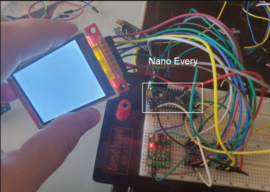
I own a Nano-Every but since it is 5V I have never used any of my SPI Protoshields with it.

Anyway, I plugged the Red Display into a breadboard. 10k Series resistors in the CS, RST, DC, MOSI, SCK, LED, MISO lines.

I amended the Adafruit example:

#define TFT_RST 8
#define TFT_DC 9
#define TFT_CS 10
#define TFT_MOSI 11
#define TFT_MISO 12
#define TFT_CLK  13

// Use hardware SPI (on Uno, #13, #12, #11) and the above for CS/DC
//Adafruit_ILI9341 tft = Adafruit_ILI9341(TFT_CS, TFT_DC, TFT_RST);  // <<<<<<<<
// If using the breakout, change pins as desired
Adafruit_ILI9341 tft = Adafruit_ILI9341(TFT_CS, TFT_DC, TFT_MOSI, TFT_CLK, TFT_RST, TFT_MISO);

The HW_SPI constructor did not work !!

So I tried the SW_SPI constructor. Which worked but very SLOW.

I then tried your UCG_Box3D.ino which fails with the HW_SPI constructor but is fine with the SW_SPI constructor (but SLOW):

Ucglib_ILI9341_18x240x320_SWSPI ucg(/*sclk=*/ 13, /*data=*/ 11, /*cd=*/ 9, /*cs=*/ 10, /*reset=*/ 8);

I am not sure what the HW_SPI problem is.
I will investigate later.

No, I am not going to try 1k0 series resistors because it would damage my display.
If you own six 4k7 resistors I will replace my 10k with 4k7.

David.

I hasn't got enough 4.7k ohm resistors so I'm using level-shifters at the moment. I can buy more 4.7k ohm resistors later.

Go on. Resistors are cheap. You can buy assorted resistors on Ebay from local sellers.

I suggest 10k for Series.
But 4k7 + 10k would be better as a voltage-divider.

David.

I repeated adafruit_ili9341 example sketch on nano every with softare SPI, and i can say that something works, display is unstable. I will buy 4k7 and 10k resistors and write results.

While I'm waiting for resistors I built a circuit with level-shifters and 1K resistors. I ran the adafruit_ili9341 example sketch on nano every in HWSPI mode and it's ok. Display works fine without problems.

graphicstest.ino (10 KB)

As I said earlier. I have only used Red 3.3V SPI displays with proper 3.3V logic Arduinos. e.g. switchable 3V/5V Uno clones, Zero, Due, STM32, Teensy3.2, Teensy4.0, ESP8266, ESP32

So I followed TFTLCDCyg's advice and soldered up a Protoshield with a CD4050. (actually SIL4050BE)

I was horrified to find that the CD4050 does NOT work with 8MHz SPI.
It seems to be ok at 4MHz SPI.

So I checked the TI CD4050 datasheet. No figures for Transition times @ 3.3V. But the 5V values were appalling. Typical 60ns @ 5V. Heaven knows the time for 3.3V ( ?? 90ns )
NXP 74HC4050 specifies typical transition times 19ns @ 2V, 9ns @ 4.5V. Which implies about 14ns @ 3.3V

@TFTLCDCyg,

Do you use CD4050B or 74HC4050 which seems to have better switching performance ?

Unfortunately, SIL4050BE was what I actually possessed.
I only need to use this Protoshield on Nano-Every, Leo, Mega2560, ... which have a maximum SPI = 10MHz.

Obviously proper 3.3V MCUs can manage SPI <= 42MHz i.e. the practical limit for the ILI9341.

David.

If you use short wiring, correctly connect each point and connect your TFT firmly, you should not see speed reductions.

You must keep in mind that you want to move a screen using poorly optimized libraries like the arduino SPI and although it is good to start with, the original adafruit library requires deep optimizations to get the best possible performance for AVR.

My suggestion is that you use the ILI9341_due library, it has optimizations that allow AVR boards to reach 80 or maybe 85% of their potential.

I don't have a nano but I have a UNO, I have the two circuits enabled in their respective shield: a CD4050BE and a set of 10K SMD resistors joined in the form of 5 voltage dividers.

If what you are looking for is a huge processing power in a few millimeters, go straight for a teensy 4 or a teensy 4.1, you have 600 Mhz at your disposal !!

I don't have a nano but I have a UNO, I have the two circuits enabled in their respective shield: a CD4050BE and a set of 10K SMD resistors joined in the form of 5 voltage dividers.

Yes, I am sure that the 10k+20k voltage dividers will work fine on the Uno. i.e. with SPI @ 8MHz

What make is your CD4050BE chip ?
CD4050 Datasheets permit 3.3V operation but don't specify any typical transition times for 3.3V

xxx74HC4050 datasheets specify times for 2V operation. These vary greatly for TI, NXP, Freescale, ...

I would be 100% certain that your CD4050 will not work on the Due. Especially with Marek's library that has SPI @ 42MHz.

David.

I use 2 simple level-shifters as you can see below (That's all that I have got for now):

https://aliexpress.ru/item/4000089382375.html?spm=a2g0o.search0302.0.0.624774ec7RFSvp&algo_pvid=17d3511c-6217-4a50-812c-f12de24e3b49&algo_expid=17d3511c-6217-4a50-812c-f12de24e3b49-0&btsid=0b8b035616167920074572427e05bf&ws_ab_test=searchweb0_0,searchweb201602_,searchweb201603_&sku_id=10000000237768954