Hi guys,
I'm basically brand new at all this. Yesterday I watched a tutorial on how to write my own code for a blink (I know Arduino has the examples but trying to refrain from relying on them)
Today's lesson was to successfully light up my LedPin (13) by using a button that i have wired into my breadboard.
Now I've got the code correct because i verified it but there must be an issue with the layout. It's all down to me not understanding my breadboard. I've taken photos and attached them below. I'm sorry for being such a novice.
Equipment
SainSmart Uno
Experiementor 350 Breadboard
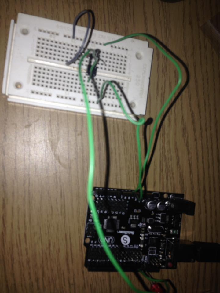
I have attached the images of my setup and posted my code below so you can at least try and understand where I placed these.
int switchPin = 8;
int ledPin = 13;

void setup()
{
  pinMode(switchPin, INPUT);
  pinMode(ledPin, OUTPUT);
}

void loop()
{
  if (digitalRead(switchPin) == HIGH)
{
    digitalWrite(ledPin, HIGH);
  }
  else
  {
    digitalWrite(ledPin, LOW);
I spotted one mistake - you didn't close the loop with two }
Yeah i realised after I copied and pasted it.
Anywho, it still isn't working. I'm really not sure how the setup of my breadboard works. Which side is ground etc etc. I could use some form of diagram for my specific breadboard to help me understand what goes where.
In your first picture the switchPin is on pin 12 not pin 8 like your code states.
The last pic of the breadboard and button the wire isn't connected to one of the pins on the switch, it looks like it is in between the two pins.
I really can't tell which is power and which is ground to orient where the resistor should go.
I yeah, ignore them I was faffing around with it. But you're right I don't know which is power and ground to orient the resistor either. I just can't seem to find any layouts of my breadboard. The code and the wires aren't an issue I know where to place them from the Arduino and the breadboard. I just don't know what the layout of my breadboard is. If that makes any sense. I followed Jeremy Blum's Arduino Tutorial 2 video.
Don't avoid the examples. They are really one of the quickest ways to learn. Using code that is already mostly debugged will get your projects started much faster.
For example, any time you buy a new sensor, you will probably have a library provided for that sensor. How do you learn how to use the library? Just load up one of the examples that came with the library. This also has the benefit that you can test your sensor with some simple wiring (all other sensors/shields disconnected) and get an idea of what the output is supposed to look like.
Breadboards are not obvious are they? They seem so universal and everyone uses them without thinking too much. The main area in the center of the breadboard is connected in short 'horizontal' strips. This is so you can plug a chip into the center and connect 4-5 wires to each pin on the chip. They aren't joined across the middle because that would join the pins on the chip. The red+blue holes down the side are connected in only 4 vertical strips. This is so you can connect power and ground at one end and access that power all the way down the board. Beware some breadboards break the long strips in the middle, so watch for that.