Grumpy_Mike:
Simply put a pot on the front end. Feed the line output to the two ends of the pot and the wiper to the input of the chip.
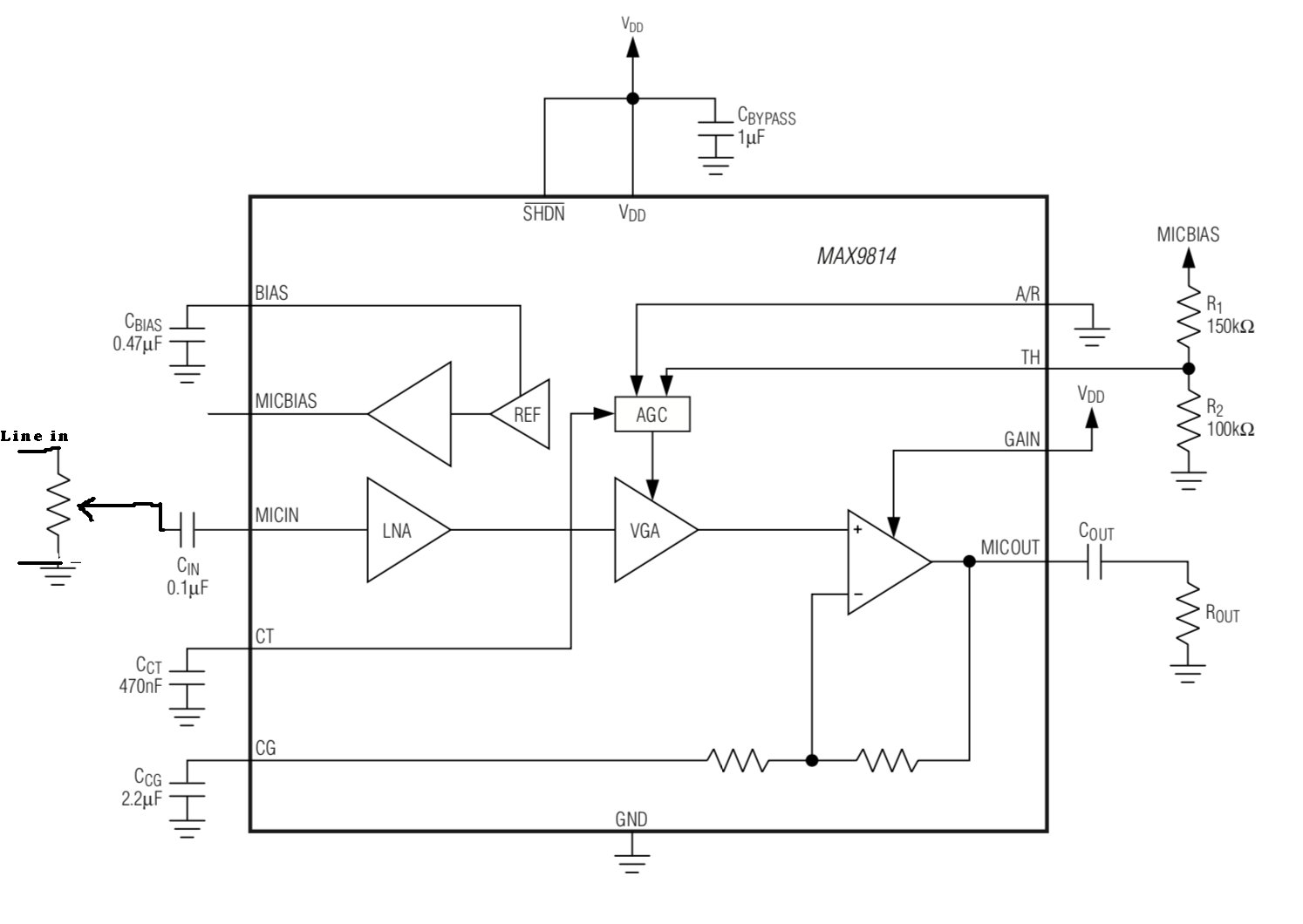
Sorry i am not sure i fully understand. So in the MAX9814 datasheet (page 11) you can see the mic simply connects to 'MICIN' with a series capacitor and there's also a parallel connection going to 'MICBIAS' with series resistor.
Is 'MICIN' the input of the chip you are referring to? Is what your saying basically replacing the this small circuit including the mic? I'm guessing a series capacitor would still be needed for MICIN.
Thanks. Well that is exactly what you said, i didn't think it would be that simple.
I just have a few more things to clarify.
So both the two ends going into the pot are the left and right line in channels?
If so do we also remove the ground seen on the bottom line coming in?
Is having the pot connected like that effectively an adjustable voltage divider?
Should i still have something like a 47mf in series on the line inputs?
You'll notice on my post #10 schematic i have a passive summer 1k resistors combining the left and right channels. Searching around i found people would use voltage dividers when taking a line signal and altering it for a mic input, is what your saying essentially the same thing?
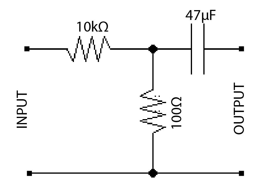
Here's one common example i have seen which says this divides the signal by a factor of 100
So both the two ends going into the pot are the left and right line in channels?
If so do we also remove the ground seen on the bottom line coming in
No you don’t remove the ground, that circuit is for a single line input. If you want to have two channels you have to mix them down to mono first. You can do this with an op amp and three or four resistors, google around for the schematic.
Is having the pot connected like that effectively an adjustable voltage divider?
Yes exactly.
Searching around i found people would use voltage dividers when taking a line signal and altering it for a mic input, is what your saying essentially the same thing?
Grumpy_Mike:
If you want to have two channels you have to mix them down to mono first. You can do this with an op amp and three or four resistors, google around for the schematic.
Well there should be a ground wire coming off that audio jack. Resistor values look fine.
Also the circuit, as it stands, needs what is called a split rail power supply. That is it has a positive output, ground and negitave output.
To convert it into a single ended supply circuit you need to make a common ground with two 1K resistors in series from the +ve to -ve of your supply, with the op amp's power lines also connected to the supply. The signal ground, that is the ground from the audio jack and pin 3 of the op-amp need to be connected to the center point of these two resistors. Also I would put a capacitor, at least 10uF across each of these resistors.
This creates an artificial signal ground so you don't need a split supply.
Grumpy_Mike:
make a common ground with two 1K resistors in series from the +ve to -ve of your supply, with the op amp's power lines also connected to the supply. The signal ground, that is the ground from the audio jack and pin 3 of the op-amp need to be connected to the center point of these two resistors. Also I would put a capacitor, at least 10uF across each of these resistors.
I followed this closely. The only part i'm not so sure about is the capacitor placement and taking polarity into account.
Grumpy_Mike:
I would wire pin 3 of the pot to pin 3 of the op amp.
Thanks. I went and made this up on a breadboard but testing shows something is wrong. It appears to have a very limited range to the point where unless the pot and the source device volume is set in exactly the right spot, the MSGEQ7 would either be peaking out or getting nothing.
I couldn't find anywhere to buy the max9814 chip itself, so i modified the breakout board as pictured. The dark blue goes directly to MICIN and the light blue goes directly to MICBIAS. The mic itself was also moved to the bread board and i have a switch to toggle between mic and line input.
From the pic you can see i removed two surface mount components (RMICBIAS and Cin). These have been substituted back into the circuit on the breadboard.
Using it as intended with the mic still works but it shows some noise. I suspect this is due to the breadboard wiring that's now present between the mic and the max9814 chip.
The only pot i had to use was a 2.2k, should i be using something higher such as a 10k?
Grumpy_Mike:
No.
The decay of the signal output from the chip is proportional to how often you read the samples. The more you read it the mode the output from the filters drop. So repeated reading will give you less and less signal each time, which is exactly what you don't want.
I don't understand this point, I read through all the posts on this thread and it came up frequently. Wouldn't resetting the MSGEQ7 then strobing the values be the correct method of taking another reading (the read value will be the full value)? I'm not sure what decay time is meant in this case. So the output decays by 10% for every read after the first if not reset? In that case why not just reset before taking consecutive samples?
I'm interested in the idea of using an AGC. Software implementation I assume is used with conjunction with for instance a digital potentiometer to control the gain of an amplifier who's output goes into Vin of the MSGEQ7. I've briefly searched for hardware AGCs for arduino but didn't find anything.
Wouldn't resetting the MSGEQ7 then strobing the values be the correct method of taking another reading (the read value will be the full value)?
No. The reset only resets the multiplexers not the peak detectors.
I'm not sure what decay time is meant in this case.
It means that each time a multiplexer reads a specific peak detector the peak detector is discharged a bit.
So the output decays by 10% for every read after the first
Yes.
if not reset?
No. The reset just resets the multiplexers sequence. So suppose you only want to read the first four filters, then you read the chip four times, toggle the reset and then the next four readings will again be the first four filters.
I've briefly searched for hardware AGCs for arduino but didn't find anything.
Seeing as an AGC is something on a linear amplifier you will not find anything concerning an AGC on an Arduino because that is a digital device.
Grumpy_Mike:
No. The reset only resets the multiplexers not the peak detectors.
It means that each time a multiplexer reads a specific peak detector the peak detector is discharged a bit.
Yes.
No. The reset just resets the multiplexers sequence. So suppose you only want to read the first four filters, then you read the chip four times, toggle the reset and then the next four readings will again be the first four filters.
Seeing as an AGC is something on a linear amplifier you will not find anything concerning an AGC on an Arduino because that is a digital device.
Read the MSGEQ7's data sheet.
I've read through the datasheet on multiple occasions, and I just reread the part under "Multiplexor Operation" now. The decay makes sense to me if an audio signal is applied then removed (or better to say grounded). The chip would hold the last peaks of the different frequencies. Since Vin would equal 0 Volts, decaying by 10% on each consecutive read makes sense (the held values decay by 10% on every read). However during most operation (while audio is being input) there would always be a Voltage input, won't the peak detectors continuously hold onto the peak values (since they are analogue)? In this case there would be an issue when the audio stops playing, as the read peak values would lead you to think the audio gradually decayed.
Please let me know where I am misunderstanding the operation.
won't the peak detectors continuously hold onto the peak values
Only if the audio at that frequency was being held at a constant peak amplitude.
See this:-Envelope detector - Wikipedia
Notice a discharge capacitor. Reading the voltage on the capacitor takes some more charge out of it as well as the normal discharge characteristics.
In this case there would be an issue when the audio stops playing, as the read peak values would lead you to think the audio gradually decayed.
Yes that is what happens. But it is not so gradual, is that a problem?
Grumpy_Mike:
Only if the audio at that frequency was being held at a constant peak amplitude.
From referring me to the envelope detector, I'm under the impression that the DC peak values are stored in capacitors. This would obviously mean a decay time, and "wrong" peak values for when the Vin amplitudes fall quickly in relation to the decay time. I was foolishly under the impression that the chip somehow instantaneously (or better said very quickly) gets the peak values of the Vin signal and stores them perfectly until they are read. So that's incorrect. What is the "value" of the decay time? The data sheet says "variable decay time". Is it the RC circuit that controls the oscillator frequency?
See this:-Envelope detector - Wikipedia
Notice a discharge capacitor. Reading the voltage on the capacitor takes some more charge out of it as well as the normal discharge characteristics.
Yes of coarse.
Yes that is what happens. But it is not so gradual, is that a problem?
How do you mean? Won't it be exponential decay coupled with regular RC decay (also exponential)? Regardless I don't understand how the output decays if Vin >> 0Vpp.
From referring me to the envelope detector, I'm under the impression that the DC peak values are stored in capacitors. This would obviously mean a decay time, and "wrong" peak values for when the Vin amplitudes fall quickly in relation to the decay time. I was foolishly under the impression that the chip somehow instantaneously (or better said very quickly) gets the peak values of the Vin signal and stores them perfectly until they are read.
The datasheet is short on details but it's a spectrum analyzer effect chip. It's not intended as a scientific spectrum analyzer instrument. I wouldn't expect "perfection". (And of course even scientific/engineering tools instruments have error/tolerance.)
So that's incorrect. What is the "value" of the decay time? The data sheet says "variable decay time". Is it the RC circuit that controls the oscillator frequency? Regardless I don't understand how the output decays if Vin >> 0Vpp.
I would expect constant-input to give constant-output. You might want to do your own experiments. For example, you can generate some test-tone files of known-frequency and known-duration (or white or pink noise) with [u]Audacity[/u] to see how it responds.
DVDdoug:
The datasheet is short on details but it's a spectrum analyzer effect chip. It's not intended as a scientific spectrum analyzer instrument. I wouldn't expect "perfection". (And of course even scientific/engineering tools instruments have error/tolerance.)
Yeah of course, I meant perfection in terms of the DC voltage being stored doesn't vary depending on when you measure it. I guess then that's what I'm after. I want to decompose the signal into it's frequencies, bands, or similar in real time. I guess FFT on the audio file being played could work (sounds like an interesting project), but that would require a decent cpu? (Esp32 could handle it I assume?)
I would expect constant-input to give constant-output. You might want to do your own experiments. For example, you can generate some test-tone files of known-frequency and known-duration (or white or pink noise) with [u]Audacity[/u] to see how it responds.
The first quote reply pretty much answers this. What I meant is say you have a high amplitude on a certain frequency band, and then the amplitude of that same frequency band drops within a short span (relative to the decay time) to a much lower value; from what I understand about the chip, the output peak value of that frequency band would be more than the latter amplitude due to decay time. Could this be solved by grounding the output pin after making a reading (to fully discharge the capacitor)? Would this damage the chip?
Currently I am away from my electronics hardware, so I am unable to test these things. Although I did test the chip with a monotone frequency input using a browser sine generator, and the chip reacts as expected. Not too sure how I'd go about testing whether the decay time is slow enough to affect consecutive readings.
Probably as there are bound to be some buffer in the way.
Basically I think this is not the chip for you. It is only a seriese of second order filters after all. However I don’t know what you do want, an FFT will only take a snapshot of a waveform not the whole sound.