Hello,
I'm working on a spectrum analyzer project using the MSGEQ7 CMOS chip (datasheet attached). I designed the attached circuit to read sounds from the MAX9814 (datasheet attached) microphone and used a voltage divider to drop the output voltage of the mic into the 300mV range required by the MSGEQ7 chip. I left the gain of the MAX9814 mic floating to keep it at 60dB. Pins 4 and 7 on the MSGEQ7 are attached to digital I/O slots 48 and 53, and pin 3 is attached to A0 on an arduino mega2560 board.
The code I'm using to read out is here:
int strobePin  = 48;    // Strobe Pin on the MSGEQ7
int resetPin   = 53;    // Reset Pin on the MSGEQ7
int outPin     = A0;   // Output Pin on the MSGEQ7
int level[7];          // An array to hold the values from the 7 frequency bands

void setup() {

 Serial.begin (9600);

  // Define our pin modes
  pinMode      (strobePin, OUTPUT);
  pinMode      (resetPin,  OUTPUT);
  pinMode      (outPin,    INPUT);

  // Create an initial state for our pins
  digitalWrite (resetPin,  LOW);
  digitalWrite (strobePin, LOW);
  delay        (1);

  // Reset the MSGEQ7 as per the datasheet timing diagram
  digitalWrite (resetPin,  HIGH);
  delay        (1);
  digitalWrite (resetPin,  LOW);
  digitalWrite (strobePin, HIGH);
  delay        (1);

}

void loop() {
 // Cycle through each frequency band by pulsing the strobe.
  for (int i = 0; i < 7; i++) {
    digitalWrite       (strobePin, LOW);
    delayMicroseconds  (100);                  // Delay necessary due to timing diagram
    level[i] =         analogRead (outPin);
    digitalWrite       (strobePin, HIGH);
    delayMicroseconds  (1);                    // Delay necessary due to timing diagram
  }

  for (int i = 0; i < 7; i++) {
    Serial.print       (level[i]);
    Serial.print       ("   ");
  }

  Serial.println ();

}
The output of this code is just 7 constants reading 538 from each frequency band. The two main problems with the circuit I've found so far are:
1: The voltage on the o.1uF capacitor connecting to pin 5 of the MSGEQ7 reads about 3.87V between pin 5 and the capacitor and 0.2mV between the capacitor and the voltage divider. This made me think the voltage divider is working correctly, but MSGEQ7 is somehow outputting a voltage at pin 5 and is not accepting the input. The 0.2mV voltage at the voltage divider does change based on the mic picking up noises.
2: The MAX9814 mic only seems to pick up sound from directly tapping on it and not anything else like clapping/talking/ambient noise/etc. Tapping the mic was having an effect on the voltage output from the MAX9814 mic and voltage at the voltage divider so I think this portion is working as intended, but I'm not sure why it isn't picking up other sounds despite being set on the highest gain setting. Online comments made the mic seem to be pretty sensitive.
Questions:
-Why is there an output voltage (the 3.87V) from pin 5 of the MSGEQ7 when it should just be receiving an input?
-Is there a problem with my circuit or potentially the MAX9814 mic that is causing it not to pick up noise other than tapping?
Any help with these questions or other things you notice would be greatly appreciated, thank you :).
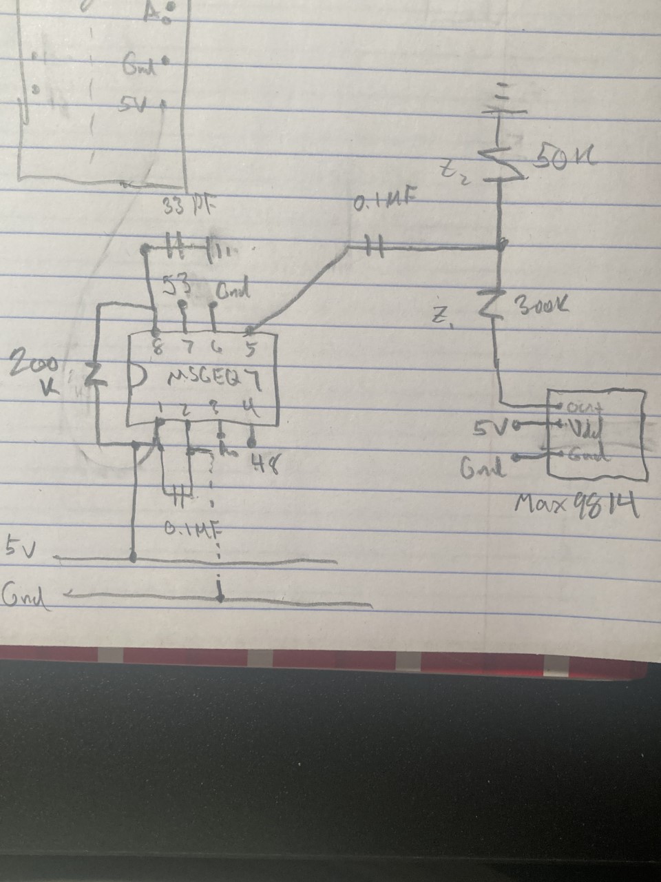
Sorry if my circuit drawing is hard to understand, I'm drawing it up in eagle and will update with that soon.
MSGEQ7 7-band EQ chip.pdf (146 KB)
MAX9814 datasheet.pdf (1.22 MB)
