To select the appropiate shunt resistor you need to use the following equation:
R_shunt_max <= ShuntVoltageInputRange_Max/I_sense_max
The shunt voltage input range max is listed in the electrical characteristics section of the data sheet. For the INA219 datasheet these values are:
Note 1: Some devices can have a different name for the shunt voltage input, for the INA229, for example, this parameters is named as V_DIFF:
As you can see, the INA219 has four different shunt voltage input ranges, the selection of each range can be modified changing certain register settings, in specific the CONFIGURATION register (0x00), bits 11 and 12. (see page 19 of the datasheet).
So according to the figure 1, what PGA gain or what input voltage range do you want to use?
If you select a range of ±40mV then the maximum shunt resistor should be:
R_shunt_max ≤ 40mV/10A
R_shunt_max ≤ 4 mΩ
The maximum power dissipation would be:
P = I^2 x R = (10A)^2 * (0.004) = 0.4W
If you select a range of ±80mV then the maximum shunt resistor should be:
R_shunt_max ≤ 80mV/10A
R_shunt_max ≤ 8 mΩ
The maximum power dissipation would be:
P = I^2 x R = (10A)^2 * (0.008) = 0.8W
If you select a range of ±160mV then the maximum shunt resistor should be:
R_shunt_max ≤ 160mV/10A
R_shunt_max ≤ 16 mΩ
The maximum power dissipation would be:
P = I^2 x R = (10A)^2 * (0.016) = 1.6W
If you select a range of ±320mV then the maximum shunt resistor should be:
R_shunt_max ≤ 320mV/10A
R_shunt_max ≤ 32 mΩ
The maximum power dissipation would be:
P = I^2 x R = (10A)^2 * (0.032) = 3.2W
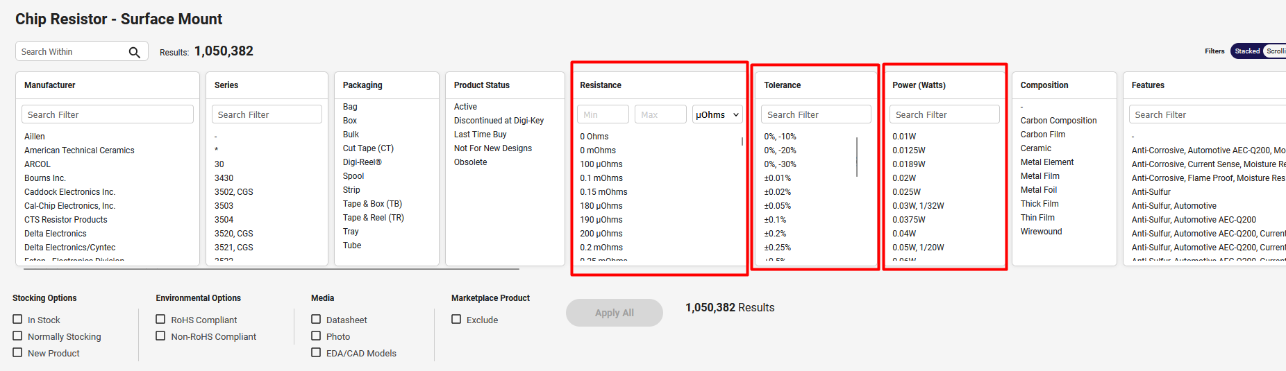
And about the physical component, you can use Digikey
Use the filters to select the resistance, the power and the tolerance
For example, for a 10mOhm, 1W resistor, 1% tolerance: